Nissan Murano Z51 (2012 year). Manual - part 57
 

  Index      Manuals     Nissan Murano Z51 (2012 year) - Service and Repair Manual


Search            copyright infringement  


Content      ..     55      56      57      58     ..


Nissan Murano Z51 (2012 year). Manual - part 57


MWI-24

< SYSTEM DESCRIPTION >

METER SYSTEM

WARNING LAMPS/INDICATOR LAMPS : Component Description

INFOID:0000000007543088

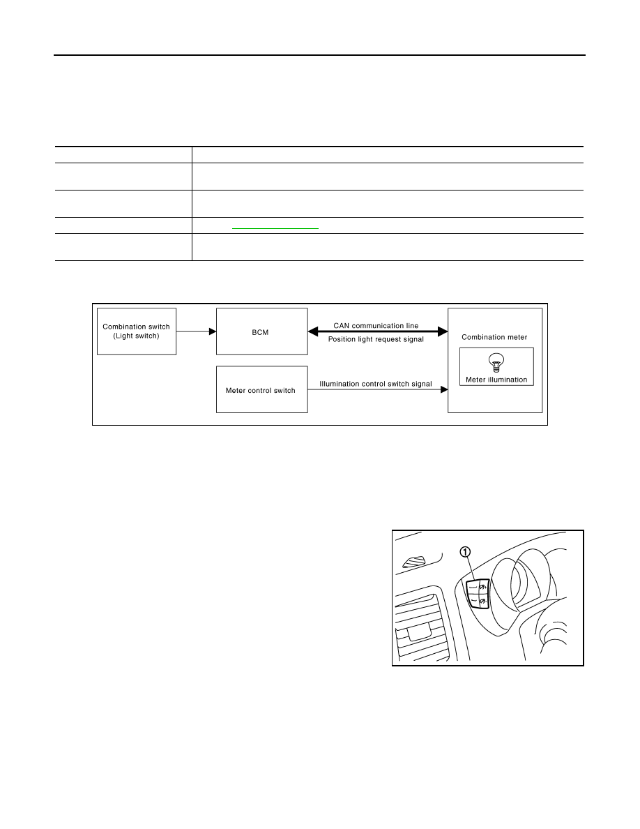
METER ILLUMINATION CONTROL

METER ILLUMINATION CONTROL : System Diagram

INFOID:0000000007543089

METER ILLUMINATION CONTROL : System Description

INFOID:0000000007543090

SYSTEM DESCRIPTION

The combination meter controls the meter illumination by the illumination control switch signal from the meter
control switch and the position light request signal transmitted by the BCM via CAN communication.

Daytime Mode

Meter illumination level can be adjusted in 22 steps using the illumi-
nation control switch (1) in daytime mode.

Nighttime Mode

• Combination meter changes the meter illumination to the nighttime mode by the position light request signal

from BCM via CAN communication.

• Meter illumination can be adjusted in 22 steps using the illumination control switch in nighttime mode.

Driver Welcome Function

Ring illumination gradually turns ON when a driver gets in the vehicle with intelligent key and closes the driver
side door.
NOTE:
Ring illumination gradually turns OFF when not turning the ignition switch ON at a certain period of time.

A.

Lower right side of rear seat

B.

Engine room (RH)

C.

Engine front side

D.

Engine room (LH)

E.

Front bumper (left back)

F.

Engine room (LH)

G.

Engine room (LH)

H.

Behind the combination meter

I.

Lower left side of rear seat

Unit

Description

Combination meter

Turns the oil pressure warning lamp ON/OFF according to the oil pressure switch signal received 
from BCM via CAN communication. 

IPDM E/R

Reads the ON/OFF signals from the oil pressure switch and transmits the oil pressure switch signal 
to the combination meter via BCM and CAN communication. 

Oil pressure switch

Refer to 

MWI-52, "Description"

BCM

Transmits the oil pressure switch signal received from IPDM E/R via CAN communication to the 
combination meter via CAN communication. 

JPNIA0746GB

JPNIA0742ZZ

Revision: 2013 February

2012 MURANO

MWI

METER SYSTEM

MWI-25

< SYSTEM DESCRIPTION >

C

D

E

F

G

H

I

J

K

L

M

B

A

O

P

Dial Effects Function

Combination meter detects the engine start when input engine speed signal at first. Pointers of speed meter
and tachometer sweep and ring illumination gradually turns ON when combination meter detects the engine
start. Then, combination meter starts the normal control.
NOTE:
• Engine coolant temperature gauge and fuel gauge do not function.
• Dial Effects Function can be turned ON/OFF from “SETTING” on the information display.

METER ILLUMINATION CONTROL : Component Parts Location

INFOID:0000000007706077

JPNIA0813ZZ

Revision: 2013 February

2012 MURANO

MWI-26

< SYSTEM DESCRIPTION >

METER SYSTEM

METER ILLUMINATION CONTROL : Component Description

INFOID:0000000007543092

INFORMATION DISPLAY

INFORMATION DISPLAY : System Diagram

INFOID:0000000007543093

INFORMATION DISPLAY : System Description

INFOID:0000000007543094

DESCRIPTION

1.

Fuel level sensor unit (sub)

2.

ABS actuator and electric unit (con-
trol unit)

3.

Oil pressure switch

4.

TCM

5.

Ambient sensor

6.

ECM

7.

IPDM E/R

8.

BCM

9.

Combination meter

10.

Fuel level sensor unit and fuel pump 
(main)

A.

Lower right side of rear seat

B.

Engine room (RH)

C.

Engine front side

D.

Engine room (LH)

E.

Front bumper (left back)

F.

Engine room (LH)

G.

Engine room (LH)

H.

Behind the combination meter

I.

Lower left side of rear seat

Unit

Description

Combination meter

Controls the meter illumination with the illumination control switch signal from the meter control 
switch and the position light request signal from BCM via CAN communication.

BCM

Transmits the position light request signal to the combination meter via CAN communication.

Meter control switch

Transmits the following signals to the combination meter.

• Illumination control switch signal (+)

• Illumination control switch signal (–)

JPNIA0747GB

Revision: 2013 February

2012 MURANO

MWI

METER SYSTEM

MWI-27

< SYSTEM DESCRIPTION >

C

D

E

F

G

H

I

J

K

L

M

B

A

O

P

• The combination meter receives the information required for controlling the operations of the information dis-

play from the BCM via CAN communication.

• The combination meter incorporates a trip computer that displays the warning / information according to the

information received from various units.

PARKING BRAKE RELEASE WARNING

The combination meter indicates the parking brake release warning judged by the vehicle speed signal
received from the ABS actuator and electric unit (control unit) via CAN communication and the parking brake
switch signal from the parking brake switch.

Warning Operation Condition

Parking brake release warning is judged if all of the following conditions are fulfilled.
• Vehicle speed is 7 km/h (4.3 MPH) or higher
• Parking brake switch ON

LOW FUEL WARNING

The combination meter indicates the low fuel warning judged by the fuel level sensor signal received from the
fuel level sensor unit.

Warning Operation Condition

• Fuel level: Approx. 9.8   (2-5/8 US gal, 2-1/8 Imp gal) or less

LOW WASHER FLUID WARNING

The combination meter indicates the low washer fluid warning judged by the signal from the washer level
switch.

Warning Operation Condition

• Indicates the warning when the washer level switch is ON for 180 seconds or more. Stops indicating the

warning when the washer level switch is OFF for 30 seconds or more.

LOW TIRE PRESSURE WARNING

• The combination meter receives remaining low tire pressure warning lamp signal from the BCM with CAN

communication line.

• The combination meter indicates low tire pressure warning when receiving remaining low tire pressure warn-

ing lamp signal.

• The combination meter indicates low tire pressure warning judged with the low tire pressure warning lamp

signal received from the BCM.

For details, refer to 

WT-7, "System Description"

.

FUEL FILLER CAP WARNING

• The combination meter receives remaining fuel filler cap warning display signal from the ECM with CAN

communication line.

• The combination meter indicates fuel filler cap warning when receiving remaining fuel filler cap warning dis-

play signal.

• The combination meter indicates fuel filler cap warning judged with the fuel filler cap warning display signal

received from the ECM.

For details, refer to 

EC-108, "System Description"

.

DOOR OPEN WARNING

• The combination meter indicates the door open warning judged by each door switch signal received from the

BCM via CAN communication line.

INSTANTANEOUS FUEL CONSUMPTION

JSNIA0033GB

Revision: 2013 February

2012 MURANO

MWI-28

< SYSTEM DESCRIPTION >

METER SYSTEM

• The combination meter receives the fuel consumption monitor signal from the ECM and the vehicle speed

signal from the ABS actuator and electric unit (control unit) via CAN communication.

• The combination meter calculates instantaneous fuel consumption according to the fuel consumption moni-

tor signal and the vehicle speed signal received via CAN communication.

AVERAGE FUEL CONSUMPTION

• The combination meter receives the fuel consumption monitor signal from the ECM and the vehicle speed

signal from the ABS actuator and electric unit (control unit) via CAN communication.

• The combination meter calculates the average fuel consumption according to the fuel consumption monitor

signal and the vehicle speed signal received via CAN communication.

• The average fuel consumption displayed on the information display is uploaded in approximately 30-second

intervals.

NOTE:
When turning ON the ignition switch after triggering a reset or removing/installing the battery, “

−−−−

” is indi-

cated until 30-seconds/500 m (0.31 miles) of driving.

AVERAGE VEHICLE SPEED

• The combination meter receives the vehicle speed signal from the ABS actuator and electric unit (control

unit) via CAN communication.

• Measures the time while the ignition switch is ON through the combination meter.
• The combination meter the average vehicle speed according to the above signals.
• The average vehicle speed displayed on the information display is uploaded in approximately 30-second

intervals.

NOTE:
When turning ON the ignition switch after triggering a reset or removing/installing the battery, “

−−−−

” is indi-

cated until 30 seconds.

TRAVEL TIME

Measures the time while the ignition switch is ON through the combination meter.

TRAVEL DISTANCE

• The combination meter receives the vehicle speed signal from the ABS actuator and electric unit (control

unit) via CAN communication.

• The combination meter calculates the vehicle distance according to the vehicle speed signal. The vehicle

distance is displayed.

POSSIBLE DRIVING DISTANCE

The combination meter calculates possible driving distance according to the vehicle speed signal and fuel
consumption monitor signal transmitted via CAN communication and the fuel level sensor signal transmitted
from the fuel level sensor.
NOTE:
• When turning ON the ignition switch after removing/installing the battery, “

−−−−

” is indicated until 30 sec-

onds.

• The indicated values may not match each other when refueling with the ignition switch ON. Refer to 

MWI-90,

"INFORMATION DISPLAY : Description"

.

AMBIENT AIR TEMPERATURE

• The combination meter receives the ambient sensor signal from the ambient sensor.
• The combination meter calculates the ambient temperature according to the ambient sensor signal.
• The indicated temperature does not increase if the vehicle speed is less than 20 km/h (12 MPH).
NOTE:
• The ambient sensor input value that is displayed on “Data Monitor” of CONSULT is the value before the cor-

rection. It may not match the indicated temperature on the information display.

• The ambient temperature may be indicated higher than the actual temperature, depending on heat in the

engine, the road surface temperature, and so on.

SETTING

Revision: 2013 February

2012 MURANO

MWI

METER SYSTEM

MWI-29

< SYSTEM DESCRIPTION >

C

D

E

F

G

H

I

J

K

L

M

B

A

O

P

Setting item list

* : Press and hold the switch (1 second or more).

Items

Setting range

Setting unit

Description

ALERT

TIME TO REST

No setting - 6 hours

30 minutes, 

[60 minutes]*

Time to rest is displayed on the informa-
tion display if the vehicle reached the set 
travel distance.

ICY

ON/OFF

Low outside temp is displayed on the in-
formation display if the ambient tempera-
ture is 3

°

C (37

°

F) or less.

MAINTENANCE

ENGINE OIL

No setting - 18,500 miles, 
(No setting - 30,000 km)

250 miles (500 km), 

[500 miles (1,000 km)]*

The engine oil replacement interval is dis-
played on the information display if the ve-
hicle reached the set distance.

OIL FILTER

No setting - 18,500 miles, 
(No setting - 30,000 km)

250 miles (500 km), 

[500 miles (1,000 km)]*

The oil filter replacement interval is dis-
played on the information display if the ve-
hicle reached the set distance.

TIRE

No setting - 18,500 miles, 
(No setting - 30,000 km)

250 miles (500 km), 

[500 miles (1,000 km)]*

The tire replacement interval is displayed 
on the information display if the vehicle 
reached the set distance.

OTHER

No setting - 18,500 miles, 
(No setting - 30,000 km)

250 miles (500 km), 

[500 miles (1,000 km)]*

The other replacement interval is dis-
played on the information display if the ve-
hicle reached the set distance.

DISPLAY

LANGUAGE

ENGLISH/FRANCAIS

The language setting can be changed.

UNIT

US/METRIC

The unit setting can be changed.

DIAL EFFECTS

ON/OFF

The dial effects setting can be changed.

Revision: 2013 February

2012 MURANO

MWI-30

< SYSTEM DESCRIPTION >

METER SYSTEM

INFORMATION DISPLAY : Component Parts Location

INFOID:0000000007706078

JPNIA0813ZZ

1.

Fuel level sensor unit (sub)

2.

ABS actuator and electric unit (con-
trol unit)

3.

Oil pressure switch

4.

TCM

5.

Ambient sensor

6.

ECM

7.

IPDM E/R

8.

BCM

9.

Combination meter

10.

Fuel level sensor unit and fuel pump 
(main)

Revision: 2013 February

2012 MURANO

MWI

METER SYSTEM

MWI-31

< SYSTEM DESCRIPTION >

C

D

E

F

G

H

I

J

K

L

M

B

A

O

P

INFORMATION DISPLAY : Component Description

INFOID:0000000007543096

A.

Lower right side of rear seat

B.

Engine room (RH)

C.

Engine front side

D.

Engine room (LH)

E.

Front bumper (left back)

F.

Engine room (LH)

G.

Engine room (LH)

H.

Behind the combination meter

I.

Lower left side of rear seat

Unit

Description

Combination meter

Controls the information display according to the signal received from each unit.

Fuel level sensor unit

Refer to 

MWI-46, "Description"

.

ECM

Transmits the following signals to the combination meter via CAN communication.

• Engine speed signal

• Fuel filler cap warning display signal

• Fuel consumption monitor signal

ABS actuator and electric unit 
(control unit)

Transmits the vehicle speed signal to the combination meter via CAN communication.

BCM

Transmits signals provided by various units to the combination meter via CAN communication.

Meter control switch

Transmits the following signals to the combination meter.

• Enter switch signal

• Select switch signal

Washer level switch

Transmits the washer level signal to the combination meter.

Parking brake switch

Refer to 

MWI-54, "Description"

.

Door switch

Transmits the door switch signals to BCM.

IPDM E/R

Transmits the ambient sensor signal to the combination meter.

Ambient sensor

Detects the ambient air temperature and transmits the ambient sensor signal to the IPDM E/R.

Revision: 2013 February

2012 MURANO

MWI-32

< SYSTEM DESCRIPTION >

COMPASS

COMPASS

Description

INFOID:0000000007543097

DESCRIPTION

• This electronic compass is able to display 8 primary directions: N, NE, E, SE, S, SW, W, NW.
• The compass switch (1) is used to operate the compass.

Switch Operation

• All standard compasses determine direction relative to magnetic north, however, this electronic compass is

designed to display direction relative to true north.

• The difference between magnetic north and true north varies from place to place across the surface of the

earth.

• This electronic compass must be “told” approximately where it is on the earth’s surface so that the magnetic

north reading can be properly converted into a true north display.

• To tell the electronic compass where it’s at, the earth is separated into numbered “Zone Variances”. The

zone variance number in which the compass is to function must be entered into this electronic compass.

• Each zone is magnetically about 4.2

°

 wide. Typically, anything under a 22.5

°

 total zone change is not noticed

on the electronic compass display. However, if a change over 22.5

°

 occurs, a reading may be off by one or

more primary directions.

• On long trips, the vehicle may leave its original zone and enter one or more new zones. Generally, you do

not need to reset the compass zone if you travel between 3 or 4 zones, such as business travel or vacation.
The typical driver will not notice any difference on the display within 3 or 4 zones. However, if the vehicle is
“permanently” moved to a new location, it is recommended that the compass zone be reset.

ZONE VARIATION SETTING PROCEDURE

1.

Press and hold the compass switch for 3 – 9 seconds.

2.

The current zone setting appears on the compass display.

3.

Find the current geographical location number in the zone varia-
tion chart.

4.

Select the new zone number. (Press the compass switch until
the new zone number appears on the compass display.)

5.

After select the new zone number, the compass display will
automatically shows a direction within a few seconds.

6.

Perform the following calibration procedure for more accurate
indications.

Press

Compass is turned ON/OFF

Press and hold
(for 3- 9 sec.)

Compass display (2) turns to zone variation change 
mode

Press and hold (for more 
than 9 sec.)

Compass display turns to calibration mode

SKIB8868E

SEL168Y

Revision: 2013 February

2012 MURANO

MWI

COMPASS

MWI-33

< SYSTEM DESCRIPTION >

C

D

E

F

G

H

I

J

K

L

M

B

A

O

P

CALIBRATION PROCEDURE

NOTE:
The compass calibrates itself under normal driving conditions. However, occasional circumstances may cause
the compass to operate inaccurately. Example: Driving from rural (wide open) areas to crowded city areas, or
if an aftermarket (i.e., non original equipment) antenna with a magnetic base is attached to the vehicle. Cali-
brate the mirror compass if the display shows only one direction or a limited number of directions.
NOTE:
• If “magnetic hats” are used in the dealership for vehicle identification, remove the hat from the vehicle before

performing the following steps. Do not put the hat back on the vehicle after the procedure is completed.

• Drive the vehicle to an open level area; away from large metallic objects, structures, and overhead power

lines.

• Turn off “non-essential” electrical accessories (rear window defrost, heater/air conditioning, wipers) and

close the doors.

1.

Verify the correct compass zone setting for the geographical location.

2.

Press and hold the compass switch for more than 9 seconds.

3.

“C” is displayed on the compass display when calibration starts.

4.

Drive slowly [less than 8 km/h (5 MPH)] in a circle until the “C / CAL” is replaced with primary headings (N,
NE, E, SE, S, SW, W, or NW).
NOTE:
This will require driving at least 2 complete 360 degree circles, 3 complete circles may be required.

5.

The compass calibration procedure is now complete. The compass should operate normally.
NOTE:
If at any time the compass continually displays the incorrect direction or the reading is erratic or locked,
repeat the calibration procedure.

Component Parts Location

INFOID:0000000007543098

Special Repair Requirement

INFOID:0000000007543099

1.

PERFORM ZONE VARIATION SETTING

Perform the zone variation setting. Refer to 

MWI-32, "Description"

>> GO TO 2.

2.

PERFORM CALIBRATION

Perform the calibration. Refer to 

MWI-32, "Description"

.

>> Setting completion

1

: Compass switch

2

: Compass display

SKIB8868E

Revision: 2013 February

2012 MURANO

MWI-34

< SYSTEM DESCRIPTION >

DIAGNOSIS SYSTEM (METER)

DIAGNOSIS SYSTEM (METER)

Diagnosis Description

INFOID:0000000007543100

SELF-DIAGNOSIS MODE

• Information display LCD segment operation can be checked in self-diagnosis mode.
• Meters/gauges can be checked in self-diagnosis mode.

OPERATION PROCEDURE

1.

Turn ignition switch OFF.

2.

While pressing the trip reset switch (1), turn ignition switch ON.
NOTE:
If the diagnosis function is activated with “trip A” displayed, the
mileage on “trip A” is reset to “0000.0”. (The same way for “trip
B”.)

3.

Make sure that the trip meter displays “0000.0”.

4.

Press the trip reset switch at least 3 times. (Within 7 seconds
after the ignition switch is turned ON.)

5.

The unified meter control unit is turned to self-diagnosis mode.
• All the segments on the odo/trip meter and shift position indicator illuminate.
• The segment dots of the information display LCD (1) blink

alternately. 

• Engine coolant temperature gauge and fuel gauge return to

zero, simultaneously.

NOTE:
• Check combination meter power supply and ground circuit when the self-diagnosis mode of the combi-

nation meter does not start. Replace combination meter if abnormal.

• If any of the segments are not displayed, replace combination meter.

6.

Each meter activates by pressing the trip reset switch.

NOTE:

JPNIA0743ZZ

JPNIA0766ZZ

JSNIA3701ZZ

Revision: 2013 February

2012 MURANO

MWI

DIAGNOSIS SYSTEM (METER)

MWI-35

< SYSTEM DESCRIPTION >

C

D

E

F

G

H

I

J

K

L

M

B

A

O

P

• If any of the meters or gauges are not activated, replace combination meter.
• The figure is reference.

CONSULT Function (METER/M&A)

INFOID:0000000007543101

CONSULT APPLICATION ITEMS

CONSULT can perform the following diagnosis modes via CAN communication and the combination meter.

SELF DIAG RESULT

Refer to 

MWI-67, "DTC Index"

.

DATA MONITOR

Display Item List

X: Applicable

System

Diagnosis mode

Description

METER/M&A

Self Diagnostic Result

The combination meter checks the conditions and displays memorized errors.

Data Monitor

Displays the combination meter input/output data in real time.

Warning History

Lighting history of the warning lamp and indicator lamp can be checked.

Display item [Unit]

MAIN

SIGNALS

Description

SPEED METER
[km/h]

X

Value of vehicle speed signal received from ABS actuator and electric unit (control 
unit) via CAN communication.
NOTE:
655.35 is displayed when the malfunction signal is received.

SPEED OUTPUT
[km/h]

X

Vehicle speed signal value transmitted to other units via CAN communication.
NOTE:
655.35 is displayed when the malfunction signal is received.

ODO OUTPUT
[km/h or mph]

Odometer signal value transmitted to other units via CAN communication.

TACHO METER
[rpm]

X

Value of the engine speed signal received from ECM via CAN communication.
NOTE:
8191.875 is displayed when the malfunction signal is received.

FUEL METER
[L]

X

Fuel level indicated on combination meter.

W TEMP METER
[

°

C] 

X

Value of engine coolant temperature signal is received from ECM via CAN com-
munication. 
NOTE:
215 is displayed when the malfunction signal is input.

FUEL CAP W/L
[On/Off]

Status of fuel filler cap warning display detected from fuel filler cap warning display 
signal received from ECM via CAN communication.

ABS W/L
[On/Off]

Status of ABS warning lamp detected from ABS warning lamp signal is received 
from ABS actuator and electric unit (control unit) via CAN communication.

VDC/TCS IND
[On/Off]

Status of VDC OFF indicator lamp detected from VDC OFF indicator lamp signal 
is received from ABS actuator and electric unit (control unit) via CAN communica-
tion.

SLIP IND
[On/Off]

Status of VDC warning lamp detected from VDC warning lamp signal received 
from ABS actuator and electric unit (control unit) via CAN communication.

BRAKE W/L
[On/Off]

Status of brake warning lamp detected from brake warning lamp signal is received 
from ABS actuator and electric unit (control unit) via CAN communication.
NOTE:
Displays “Off” if the brake warning lamp is illuminated when the valve check starts, 
the parking brake switch is turned ON or the brake fluid level switch is turned ON.

DOOR W/L
[On/Off]

Status of door warning detected from door switch signal received from BCM via 
CAN communication.

Revision: 2013 February

2012 MURANO

MWI-36

< SYSTEM DESCRIPTION >

DIAGNOSIS SYSTEM (METER)

HI-BEAM IND
[On/Off]

Status of high beam indicator lamp detected from high beam request signal is re-
ceived from BCM via CAN communication.

TURN IND
[On/Off]

Status of turn indicator lamp detected from turn indicator signal is received from 
BCM via CAN communication.

LIGHT IND
[On/Off]

Status of light indicator lamp detected from position light request signal is received 
from BCM via CAN communication.

OIL W/L
[On/Off]

Status of oil pressure warning lamp detected from oil pressure switch signal is re-
ceived from BCM via CAN communication.

MIL
[On/Off] 

Status of malfunction indicator lamp detected from malfunctioning indicator lamp 
signal is received from ECM via CAN communication.

CRUISE IND
[On/Off]

Status of CRUISE indicator detected from ASCD status signal is received from 
ECM via CAN communication.

O/D OFF IND
[On/Off]

Status of O/D OFF indicator detected from O/D OFF indicator signal is received 
from CVT shift selector.

4WD W/L
[On/Off]

Status of AWD warning lamp detected from AWD warning lamp signal is received 
from AWD control unit via CAN communication.

4WD LOCK IND
[On/Off]

Status of AWD LOCK warning lamp detected from AWD LOCK warning lamp sig-
nal is received from AWD control unit via CAN communication.

FUEL W/L
[On/Off]

Low-fuel warning lamp status detected by the identified fuel level.

WASHER W/L
[On/Off]

Status of washer warning lamp judged from washer level switch input to combina-
tion meter.

AIR PRES W/L
[On/Off]

Status of low tire pressure warning lamp detected from TPMS malfunction warning 
lamp signal is received from BCM via CAN communication.

KEY G/W W/L
[On/Off]

Status of key warning lamp (G/Y) detected from key warning signal is received 
from BCM via CAN communication.

LCD
[B&P N, B&P I, ID NG, ROTAT, SFT 
P, INSRT, BATT, NO KY, OUTKY, LK 
WN]

Displays status of Intelligent Key system warning detected from meter display sig-
nal is received from BCM via CAN communication.

SHIFT IND
[P, R, N, D, L]

Status of shift position indicator detected from shift position signal is received from 
TCM via CAN communication.

O/D OFF SW
[On/Off] 

Status of O/D OFF switch.

M RANGE SW
[Off]

This item is displayed, but cannot be monitored.

NM RANGE SW
[Off]

This item is displayed, but cannot be monitored.

AT SFT UP SW
[Off]

This item is displayed, but cannot be monitored.

AT SFT DWN SW
[Off]

This item is displayed, but cannot be monitored.

ST SFT UP SW
[Off]

This item is displayed, but cannot be monitored.

ST SFT DWN SW
[Off]

This item is displayed, but cannot be monitored.

PKB SW
[On/Off]

Status of parking brake switch.

BUCKLE SW
[On/Off]

Status of seat belt buckle switch (driver side).

BRAKE OIL SW
[On/Off]

Status of brake fluid level switch.

Display item [Unit]

MAIN

SIGNALS

Description

Revision: 2013 February

2012 MURANO

MWI

DIAGNOSIS SYSTEM (METER)

MWI-37

< SYSTEM DESCRIPTION >

C

D

E

F

G

H

I

J

K

L

M

B

A

O

P

NOTE:

Some items are not available according to vehicle specification.

WARNING HISTORY

• Stores histories when warning/indicator lamp is turned on.
• “WARNING HISTORY” indicates the “TIME” when the warning/indicator lamp is turned on.
• The “TIME” above is:
- 0: The condition that the warning/indicator lamp has been turned on 1 or more times after starting the engine

and waiting for 30 seconds.

- 1 - 39: The number of times the engine was restarted after the 0 condition.
- NO WARNING HISTORY: Stores NO (0) turning on history of warning/indicator lamp.
NOTE:
• WARNING HISTORY is not stored for approximately 30 seconds after the engine starts.
• Brake warning lamp does not store any history when parking the brake is applied or the brake fluid level gets

low.

Display Item

DISTANCE
[km]

Value of possible driving distance calculated by combination meter.

A/C AMP CONN
[On/Off]

Status of A/C auto amp. connection recognition signal.

ENTER SW
[On/Off]

Status of 

 (ENTER) switch.

SELECT SW
[On/Off]

Status of 

 (SELECT) switch.

OUTSIDE TEMP
[

°

C or 

°

F]

Ambient air temperature value converted from ambient sensor signal received 
from ambient sensor.
NOTE:
This may not match with the temperature value indicated on the information dis-
play. (Because the information display value is a corrected value from the ambient 
sensor input value.)

FUEL LOW SIG
[On/Off]

Status of fuel level low warning signal to output to AV control unit via CAN com-
munication.

BUZZER 
[On/Off]

X

Buzzer status (in the combination meter) is detected from the buzzer output signal 
received from each unit via CAN communication and the warning output condition 
of the combination meter.

Display item [Unit]

MAIN

SIGNALS

Description

Display item

Description

ABS W/L

Lighting history of ABS warning lamp.

VDC/TCS IND

Lighting history of VDC OFF indicator lamp.

SLIP IND

Lighting history of VDC warning lamp.

BRAKE W/L

Lighting history of brake warning lamp.

DOOR W/L

Lighting history of door warning.

OIL W/L

Lighting history of oil pressure warning lamp.

C-ENG W/L

Lighting history of malfunction indicator lamp.

CRUISE IND

Lighting history of CRUISE indicator lamp.

SET IND

Lighting history of SET indicator.

O/D OFF IND 

Lighting history of O/D OFF indicator lamp.

4WD W/L

Lighting history of AWD warning lamp.

FUEL W/L

Lighting history of low fuel level warning.

WASHER W/L

Lighting history of low washer fluid warning

AIR PRES W/L

Lighting history of low tire pressure warning lamp.

Revision: 2013 February

2012 MURANO

MWI-38

< SYSTEM DESCRIPTION >

DIAGNOSIS SYSTEM (METER)

NOTE:
In items displayed on the CONSULT screen, only those listed in the above table are used.

KEY G/Y W/L

Lighting history of key warning lamp (green/yellow).

KEY R W/L

Lighting history of key warning lamp (red).

CHAGE W/L

Lighting history of charge warning lamp.

Display item

Description

Revision: 2013 February

2012 MURANO

MWI

U1000 CAN COMM CIRCUIT

MWI-39

< DTC/CIRCUIT DIAGNOSIS >

C

D

E

F

G

H

I

J

K

L

M

B

A

O

P

DTC/CIRCUIT DIAGNOSIS

U1000 CAN COMM CIRCUIT

Description

INFOID:0000000007543102

CAN (Controller Area Network) is a serial communication system for real time application. It is an on-vehicle
multiplex communication system with high data communication speed and excellent error detectability. Many
electronic control units are equipped onto vehicles, and each control unit shares information and links with
other control units during operation (not independent). In CAN communication, control units are connected
with two communication lines (CAN-H line, CAN-L line) allowing a high rate of information transmission with
less wiring. Each control unit transmits/receives data but selectively reads required data only.
CAN Communication Signal Chart. Refer to 

LAN-25, "CAN Communication Signal Chart"

.

DTC Logic

INFOID:0000000007543103

DTC DETECTION LOGIC

Diagnosis Procedure

INFOID:0000000007543104

1.

PERFORM SELF DIAGNOSTIC

1.

Turn ignition switch ON and wait for 2 seconds or more.

2.

Check “Self Diagnostic Result” of “METER/M&A”. 

Is “CAN COMM CIRCUIT” displayed?

YES

>> Refer to 

LAN-15, "Trouble Diagnosis Flow Chart"

.

NO

>> Refer to 

GI-44, "Intermittent Incident"

.

DTC

Display contents of 

CONSULT

Diagnostic item is detected when ...

Probable malfunction location

U1000

CAN COMM CIRCUIT

When combination meter is not transmitting or 
receiving CAN communication signal for 2 
seconds or more.

CAN communication system

Revision: 2013 February

2012 MURANO


Content      ..     55      56      57      58     ..