Nissan Murano Z51 (2012 year). Manual - part 48
LU-6
< PREPARATION >
PREPARATION
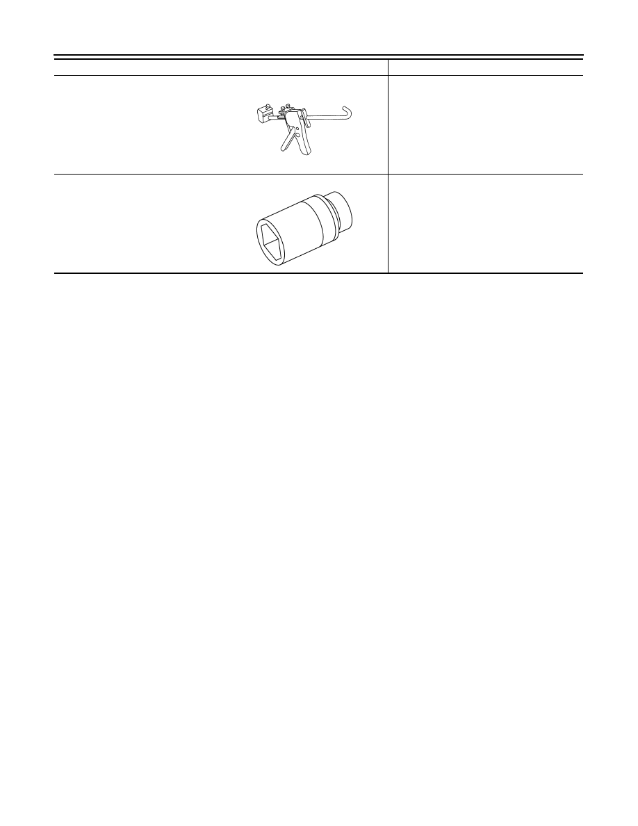
Tube presser
Pressing the tube of liquid gasket
Deep socket
Removing and installing oil pressure switch
27 mm (1.06 in)
Tool name
Description
NT052
PBIC4066E
Revision: 2013 February
2012 MURANO