Nissan Murano Z51 (2012 year). Manual - part 47
 

  Index      Manuals     Nissan Murano Z51 (2012 year) - Service and Repair Manual


Search            copyright infringement  


Content      ..     45      46      47      48     ..


Nissan Murano Z51 (2012 year). Manual - part 47


LAN

HVAC BRANCH LINE CIRCUIT

LAN-141

< DTC/CIRCUIT DIAGNOSIS >

[CAN SYSTEM (TYPE 6)]

C

D

E

F

G

H

I

J

K

L

B

A

O

P

N

HVAC BRANCH LINE CIRCUIT

Diagnosis Procedure

INFOID:0000000007544358

1.

CHECK CONNECTOR

1.

Turn the ignition switch OFF.

2.

Disconnect the battery cable from the negative terminal.

3.

Check the terminals and connectors of the A/C auto amp. for damage, bend and loose connection (unit
side and connector side).

Is the inspection result normal?

YES

>> GO TO 2.

NO

>> Repair the terminal and connector.

2.

CHECK HARNESS FOR OPEN CIRCUIT

1.

Disconnect the connector of A/C auto amp.

2.

Check the resistance between the A/C auto amp. harness connector terminals.

Is the measurement value within the specification?

YES

>> GO TO 3.

NO

>> Repair the A/C auto amp. branch line.

3.

CHECK POWER SUPPLY AND GROUND CIRCUIT

Check the power supply and the ground circuit of the A/C auto amp. Refer to the following.
• Without 7 inch display: 

HAC-77, "A/C AUTO AMP. : Diagnosis Procedure"

• With 7 inch display: 

HAC-196, "A/C AUTO AMP. : Diagnosis Procedure"

Is the inspection result normal?

YES (Present error)>>Replace the A/C auto amp. Refer to the following.

• Without 7 inch display: 

VTL-24, "Removal and Installation"

• With 7 inch display: 

VTL-87, "Removal and Installation"

YES (Past error)>>Error was detected in the A/C auto amp. branch line.
NO

>> Repair the power supply and the ground circuit.

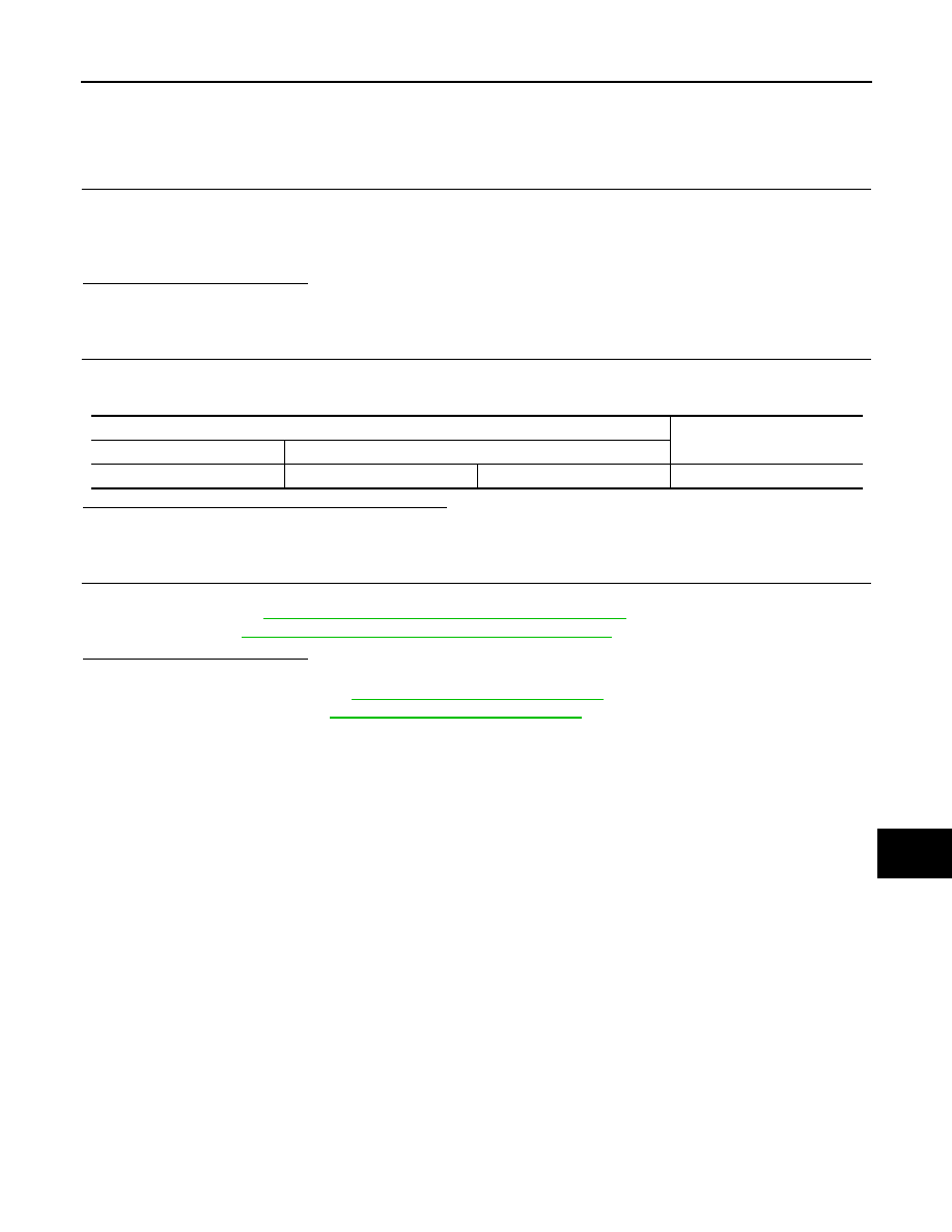
A/C auto amp. harness connector

Resistance (

)

Connector No.

Terminal No.

M50

1

2

Approx. 54 – 66

Revision: 2013 February

2012 MURANO

LAN-142

< DTC/CIRCUIT DIAGNOSIS >

[CAN SYSTEM (TYPE 6)]

M&A BRANCH LINE CIRCUIT

M&A BRANCH LINE CIRCUIT

Diagnosis Procedure

INFOID:0000000007544359

1.

CHECK CONNECTOR

1.

Turn the ignition switch OFF.

2.

Disconnect the battery cable from the negative terminal.

3.

Check the terminals and connectors of the combination meter for damage, bend and loose connection
(unit side and connector side).

Is the inspection result normal?

YES

>> GO TO 2.

NO

>> Repair the terminal and connector.

2.

CHECK HARNESS FOR OPEN CIRCUIT

1.

Disconnect the connector of combination meter.

2.

Check the resistance between the combination meter harness connector terminals.

Is the measurement value within the specification?

YES

>> GO TO 3.

NO

>> Repair the combination meter branch line.

3.

CHECK POWER SUPPLY AND GROUND CIRCUIT

Check the power supply and the ground circuit of the combination meter. Refer to 

MWI-44, "COMBINATION

METER : Diagnosis Procedure"

.

Is the inspection result normal?

YES (Present error)>>Replace the combination meter. Refer to 

MWI-94, "Removal and Installation"

.

YES (Past error)>>Error was detected in the combination meter branch line.
NO

>> Repair the power supply and the ground circuit.

Combination meter harness connector

Resistance (

)

Connector No.

Terminal No.

M34

21

22

Approx. 54 – 66

Revision: 2013 February

2012 MURANO

LAN

A-BAG BRANCH LINE CIRCUIT

LAN-143

< DTC/CIRCUIT DIAGNOSIS >

[CAN SYSTEM (TYPE 6)]

C

D

E

F

G

H

I

J

K

L

B

A

O

P

N

A-BAG BRANCH LINE CIRCUIT

Diagnosis Procedure

INFOID:0000000007544360

WARNING:

• Before servicing, turn ignition switch OFF, disconnect battery negative terminal, and wait 3 minutes

or more. (To discharge backup capacitor.)

• Never use unspecified tester or other measuring device.

1.

CHECK CONNECTOR

Check the terminals and connectors of the air bag diagnosis sensor unit for damage, bend and loose connec-
tion (unit side and connector side).

Is the inspection result normal?

YES

>> GO TO 2.

NO

>> Replace the terminal and connector.

2.

CHECK AIR BAG DIAGNOSIS SENSOR UNIT

Check the air bag diagnosis sensor unit. Refer to the following.
• For USA and CANADA: 

SRC-8, "Work Flow"

• For MEXICO: 

SRC-175, "Work Flow"

Is the inspection result normal?

YES

>> Replace the main harness.

NO

>> Replace parts whose air bag system has a malfunction.

Revision: 2013 February

2012 MURANO

LAN-144

< DTC/CIRCUIT DIAGNOSIS >

[CAN SYSTEM (TYPE 6)]

BCM BRANCH LINE CIRCUIT

BCM BRANCH LINE CIRCUIT

Diagnosis Procedure

INFOID:0000000007544361

1.

CHECK CONNECTOR

1.

Turn the ignition switch OFF.

2.

Disconnect the battery cable from the negative terminal.

3.

Check the terminals and connectors of the BCM for damage, bend and loose connection (unit side and
connector side).

Is the inspection result normal?

YES

>> GO TO 2.

NO

>> Repair the terminal and connector.

2.

CHECK HARNESS FOR OPEN CIRCUIT

1.

Disconnect the connector of BCM.

2.

Check the resistance between the BCM harness connector terminals.

Is the measurement value within the specification?

YES

>> GO TO 3.

NO

>> Repair the BCM branch line.

3.

CHECK POWER SUPPLY AND GROUND CIRCUIT

Check the power supply and the ground circuit of the BCM. Refer to 

BCS-42, "Diagnosis Procedure"

.

Is the inspection result normal?

YES (Present error)>>Replace the BCM. Refer to 

BCS-83, "Removal and Installation"

.

YES (Past error)>>Error was detected in the BCM branch line.
NO

>> Repair the power supply and the ground circuit.

BCM harness connector

Resistance (

)

Connector No.

Terminal No.

M122

91

90

Approx. 54 – 66

Revision: 2013 February

2012 MURANO

LAN

DLC BRANCH LINE CIRCUIT

LAN-145

< DTC/CIRCUIT DIAGNOSIS >

[CAN SYSTEM (TYPE 6)]

C

D

E

F

G

H

I

J

K

L

B

A

O

P

N

DLC BRANCH LINE CIRCUIT

Diagnosis Procedure

INFOID:0000000007544362

1.

CHECK CONNECTOR

1.

Turn the ignition switch OFF.

2.

Disconnect the battery cable from the negative terminal.

3.

Check the terminals and connectors of the data link connector for damage, bend and loose connection
(connector side and harness side).

Is the inspection result normal?

YES

>> GO TO 2.

NO

>> Repair the terminal and connector.

2.

CHECK HARNESS FOR OPEN CIRCUIT

Check the resistance between the data link connector terminals.

Is the measurement value within the specification?

YES (Present error)>>Check CAN system type decision again.
YES (Past error)>>Error was detected in the data link connector branch line circuit.
NO

>> Repair the data link connector branch line.

Data link connector

Resistance (

)

Connector No.

Terminal No.

M4

6

14

Approx. 54 – 66

Revision: 2013 February

2012 MURANO

LAN-146

< DTC/CIRCUIT DIAGNOSIS >

[CAN SYSTEM (TYPE 6)]

STRG BRANCH LINE CIRCUIT

STRG BRANCH LINE CIRCUIT

Diagnosis Procedure

INFOID:0000000007544363

1.

CHECK CONNECTOR

1.

Turn the ignition switch OFF.

2.

Disconnect the battery cable from the negative terminal.

3.

Check the terminals and connectors of the steering angle sensor for damage, bend and loose connection
(unit side and connector side).

Is the inspection result normal?

YES

>> GO TO 2.

NO

>> Repair the terminal and connector.

2.

CHECK HARNESS FOR OPEN CIRCUIT

1.

Disconnect the connector of steering angle sensor.

2.

Check the resistance between the steering angle sensor harness connector terminals.

Is the measurement value within the specification?

YES

>> GO TO 3.

NO

>> Repair the steering angle sensor branch line.

3.

CHECK POWER SUPPLY AND GROUND CIRCUIT

Check the power supply and the ground circuit of the steering angle sensor. Refer to 

BRC-105, "Wiring Dia-

gram -BRAKE CONTROL SYSTEM-"

.

Is the inspection result normal?

YES (Present error)>>Replace the steering angle sensor. Refer to 

BRC-128, "Removal and Installation"

.

YES (Past error)>>Error was detected in the steering angle sensor branch line.
NO

>> Repair the power supply and the ground circuit.

Steering angle sensor harness connector

Resistance (

)

Connector No.

Terminal No.

M30

5

2

Approx. 54 – 66

Revision: 2013 February

2012 MURANO

LAN

ABS BRANCH LINE CIRCUIT

LAN-147

< DTC/CIRCUIT DIAGNOSIS >

[CAN SYSTEM (TYPE 6)]

C

D

E

F

G

H

I

J

K

L

B

A

O

P

N

ABS BRANCH LINE CIRCUIT

Diagnosis Procedure

INFOID:0000000007544364

1.

CHECK CONNECTOR

1.

Turn the ignition switch OFF.

2.

Disconnect the battery cable from the negative terminal.

3.

Check the terminals and connectors of the ABS actuator and electric unit (control unit) for damage, bend
and loose connection (unit side and connector side).

Is the inspection result normal?

YES

>> GO TO 2.

NO

>> Repair the terminal and connector.

2.

CHECK HARNESS FOR OPEN CIRCUIT

1.

Disconnect the connector of ABS actuator and electric unit (control unit).

2.

Check the resistance between the ABS actuator and electric unit (control unit) harness connector termi-
nals.

Is the measurement value within the specification?

YES

>> GO TO 3.

NO

>> Repair the ABS actuator and electric unit (control unit) branch line.

3.

CHECK POWER SUPPLY AND GROUND CIRCUIT

Check the power supply and the ground circuit of the ABS actuator and electric unit (control unit). Refer to

BRC-42, "Diagnosis Procedure"

.

Is the inspection result normal?

YES (Present error)>>Replace the ABS actuator and electric unit (control unit). Refer to 

BRC-125, "Removal

and Installation"

.

YES (Past error)>>Error was detected in the ABS actuator and electric unit (control unit) branch line.
NO

>> Repair the power supply and the ground circuit.

ABS actuator and electric unit (control unit) harness connector

Resistance (

)

Connector No.

Terminal No.

E36

23

21

Approx. 54 – 66

Revision: 2013 February

2012 MURANO

LAN-148

< DTC/CIRCUIT DIAGNOSIS >

[CAN SYSTEM (TYPE 6)]

TCM BRANCH LINE CIRCUIT

TCM BRANCH LINE CIRCUIT

Diagnosis Procedure

INFOID:0000000007544365

1.

CHECK CONNECTOR

1.

Turn the ignition switch OFF.

2.

Disconnect the battery cable from the negative terminal.

3.

Check the following terminals and connectors for damage, bend and loose connection (unit side and con-
nector side).

-

TCM

-

Harness connector F123

-

Harness connector E6

Is the inspection result normal?

YES

>> GO TO 2.

NO

>> Repair the terminal and connector.

2.

CHECK HARNESS FOR OPEN CIRCUIT

1.

Disconnect the connector of TCM.

2.

Check the resistance between the TCM harness connector terminals.

Is the measurement value within the specification?

YES

>> GO TO 3.

NO

>> Repair the TCM branch line.

3.

CHECK POWER SUPPLY AND GROUND CIRCUIT

Check the power supply and the ground circuit of the TCM. Refer to 

TM-82, "Diagnosis Procedure"

.

Is the inspection result normal?

YES (Present error)>>Replace the TCM. Refer to 

TM-149, "Removal and Installation"

.

YES (Past error)>>Error was detected in the TCM branch line.
NO

>> Repair the power supply and the ground circuit.

TCM harness connector

Resistance (

)

Connector No.

Terminal No.

F23

32

31

Approx. 54 – 66

Revision: 2013 February

2012 MURANO

LAN

IPDM-E BRANCH LINE CIRCUIT

LAN-149

< DTC/CIRCUIT DIAGNOSIS >

[CAN SYSTEM (TYPE 6)]

C

D

E

F

G

H

I

J

K

L

B

A

O

P

N

IPDM-E BRANCH LINE CIRCUIT

Diagnosis Procedure

INFOID:0000000007544366

1.

CHECK CONNECTOR

1.

Turn the ignition switch OFF.

2.

Disconnect the battery cable from the negative terminal.

3.

Check the terminals and connectors of the IPDM E/R for damage, bend and loose connection (unit side
and connector side).

Is the inspection result normal?

YES

>> GO TO 2.

NO

>> Repair the terminal and connector.

2.

CHECK HARNESS FOR OPEN CIRCUIT

1.

Disconnect the connector of IPDM E/R.

2.

Check the resistance between the IPDM E/R harness connector terminals.

Is the measurement value within the specification?

YES

>> GO TO 3.

NO

>> Repair the IPDM E/R branch line.

3.

CHECK POWER SUPPLY AND GROUND CIRCUIT

Check the power supply and the ground circuit of the IPDM E/R. Refer to 

PCS-18, "Diagnosis Procedure"

.

Is the inspection result normal?

YES (Present error)>>Replace the IPDM E/R. Refer to 

PCS-34, "Removal and Installation"

.

YES (Past error)>>Error was detected in the IPDM E/R branch line.
NO

>> Repair the power supply and the ground circuit.

IPDM E/R harness connector

Resistance (

)

Connector No.

Terminal No.

E11

40

39

Approx. 108 – 132

Revision: 2013 February

2012 MURANO

LAN-150

< DTC/CIRCUIT DIAGNOSIS >

[CAN SYSTEM (TYPE 6)]

CAN COMMUNICATION CIRCUIT

CAN COMMUNICATION CIRCUIT

Diagnosis Procedure

INFOID:0000000007544367

1.

CONNECTOR INSPECTION

1.

Turn the ignition switch OFF.

2.

Disconnect the battery cable from the negative terminal.

3.

Disconnect all the unit connectors on CAN communication system.

4.

Check terminals and connectors for damage, bend and loose connection.

Is the inspection result normal?

YES

>> GO TO 2.

NO

>> Repair the terminal and connector.

2.

CHECK HARNESS CONTINUITY (SHORT CIRCUIT)

Check the continuity between the data link connector terminals.

Is the inspection result normal?

YES

>> GO TO 3.

NO

>> Check the harness and repair the root cause.

3.

CHECK HARNESS CONTINUITY (SHORT CIRCUIT)

Check the continuity between the data link connector and the ground.

Is the inspection result normal?

YES

>> GO TO 4.

NO

>> Check the harness and repair the root cause.

4.

CHECK ECM AND IPDM E/R TERMINATION CIRCUIT

1.

Remove the ECM and the IPDM E/R.

2.

Check the resistance between the ECM terminals.

3.

Check the resistance between the IPDM E/R terminals.

Is the measurement value within the specification?

YES

>> GO TO 5.

NO

>> Replace the ECM and/or the IPDM E/R.

5.

CHECK SYMPTOM

Connect all the connectors. Check if the symptoms described in the “Symptom (Results from interview with
customer)” are reproduced. 

Data link connector

Continuity

Connector No.

Terminal No.

M4

6

14

Not existed

Data link connector

Ground

Continuity

Connector No.

Terminal No.

M4

6

Not existed

14

Not existed

ECM

Resistance (

)

Terminal No.

98

97

Approx. 108 – 132

IPDM E/R

Resistance (

)

Terminal No.

40

39

Approx. 108 – 132

LKIA0037E

Revision: 2013 February

2012 MURANO

LAN

CAN COMMUNICATION CIRCUIT

LAN-151

< DTC/CIRCUIT DIAGNOSIS >

[CAN SYSTEM (TYPE 6)]

C

D

E

F

G

H

I

J

K

L

B

A

O

P

N

Inspection result

Reproduced>>GO TO 6.
Non-reproduced>>Start the diagnosis again. Follow the trouble diagnosis procedure when past error is

detected.

6.

CHECK UNIT REPRODUCTION

Perform the reproduction test as per the following procedure for each unit.
1.

Turn the ignition switch OFF.

2.

Disconnect the battery cable from the negative terminal.

3.

Disconnect one of the unit connectors of CAN communication system.
NOTE:
ECM and IPDM E/R have a termination circuit. Check other units first.

4.

Connect the battery cable to the negative terminal. Check if the symptoms described in the “Symptom
(Results from interview with customer)” are reproduced. 
NOTE:
Although unit-related error symptoms occur, do not confuse them with other symptoms. 

Inspection result

Reproduced>>Connect the connector. Check other units as per the above procedure.
Non-reproduced>>Replace the unit whose connector was disconnected.

Revision: 2013 February

2012 MURANO

LU-1

ENGINE

C

D

E

F

G

H

I

J

K

L

M

SECTION 

LU

A

LU

N

O

P

CONTENTS

ENGINE LUBRICATION SYSTEM

SYSTEM DESCRIPTION  ..............................

2

DESCRIPTION ....................................................

2

Engine Lubrication System ......................................

2

Engine Lubrication System Schematic ......................

3

PRECAUTION ...............................................

4

PRECAUTIONS ...................................................

4

Precaution for Liquid Gasket .....................................

4

PREPARATION ............................................

5

PREPARATION ...................................................

5

Special Service Tool  .................................................

5

Commercial Service Tool  ..........................................

5

PERIODIC MAINTENANCE ..........................

7

ENGINE OIL  ........................................................

7

Inspection ..................................................................

7

Draining .....................................................................

8

Refilling .....................................................................

9

OIL FILTER  ........................................................

10

Removal and Installation .........................................

10

Inspection ................................................................

10

REMOVAL AND INSTALLATION  ...............

11

OIL COOLER  ....................................................

11

Exploded View .........................................................

11

Removal and Installation  .........................................

11

Inspection ................................................................

12

UNIT DISASSEMBLY AND ASSEMBLY  ....

13

OIL PUMP  .........................................................

13

Exploded View .........................................................

13

Removal and Installation  .........................................

13

Disassembly and Assembly .....................................

13

Inspection ................................................................

14

SERVICE DATA AND SPECIFICATIONS 
(SDS) ............................................................

16

SERVICE DATA AND SPECIFICATIONS 
(SDS) .................................................................

16

Periodical Maintenance Specification ....................

16

Engine Oil Pressure ...............................................

16

Oil Pump .................................................................

16

Regulator Valve ......................................................

16

Revision: 2013 February

2012 MURANO

LU-2

< SYSTEM DESCRIPTION >

DESCRIPTION

SYSTEM DESCRIPTION

DESCRIPTION

Engine Lubrication System

INFOID:0000000007541123

JPBIA1773GB

Revision: 2013 February

2012 MURANO

DESCRIPTION

LU-3

< SYSTEM DESCRIPTION >

C

D

E

F

G

H

I

J

K

L

M

A

LU

N

P

O

Engine Lubrication System Schematic

INFOID:0000000007541124

JPBIA1775GB

Revision: 2013 February

2012 MURANO

LU-4

< PRECAUTION >

PRECAUTIONS

PRECAUTION

PRECAUTIONS

Precaution for Liquid Gasket

INFOID:0000000007541125

LIQUID GASKET APPLICATION PROCEDURE

1.

Remove old liquid gasket adhering to the liquid gasket application surface and the mating surface.
• Remove liquid gasket completely from the liquid gasket application surface, mounting bolts, and bolt

holes.

2.

Wipe the liquid gasket application surface and the mating surface with white gasoline (lighting and heating
use) to remove adhering moisture, grease and foreign materials.

3.

Apply liquid gasket to the liquid gasket application surface.
Use Genuine RTV Silicone Sealant or equivalent. Refer to 

GI-22, "Recommended Chemical Prod-

ucts and Sealants"

.

• Within 5 minutes of liquid gasket application, install in the mating component.
• If liquid gasket protrudes, wipe it off immediately.
• Never retighten mounting bolts or nuts after the installation.
• After 30 minutes or more have passed from the installation, fill engine oil and engine coolant.

Revision: 2013 February

2012 MURANO

PREPARATION

LU-5

< PREPARATION >

C

D

E

F

G

H

I

J

K

L

M

A

LU

N

P

O

PREPARATION

PREPARATION

Special Service Tool

INFOID:0000000007541126

The actual shapes of Kent-Moore tools may differ from those of special service tools illustrated here.

Commercial Service Tool

INFOID:0000000007541127

Tool number
(Kent-Moore No.)
Tool name

Description

ST25051001
(J-25695-1)
Oil pressure gauge

Measuring oil pressure
Maximum measuring range: 2,452 kPa (25 

kg/cm

2

, 356 psi)

ST25052000
(J-25695-2)
Hose

Adapting oil pressure gauge to oil pan (upper)

KV10115801
(J-38956)
Oil filter wrench

Removing oil filter
a: 64.3 mm (2.531 in)

NT050

S-NT559

S-NT375

Tool name

Description

Power tools

Loosening nuts and bolts

PBIC0190E

Revision: 2013 February

2012 MURANO


Content      ..     45      46      47      48     ..