Nissan Murano Z51 (2012 year). Manual - part 38
IP-20
< REMOVAL AND INSTALLATION >
CENTER CONSOLE ASSEMBLY
CENTER CONSOLE ASSEMBLY
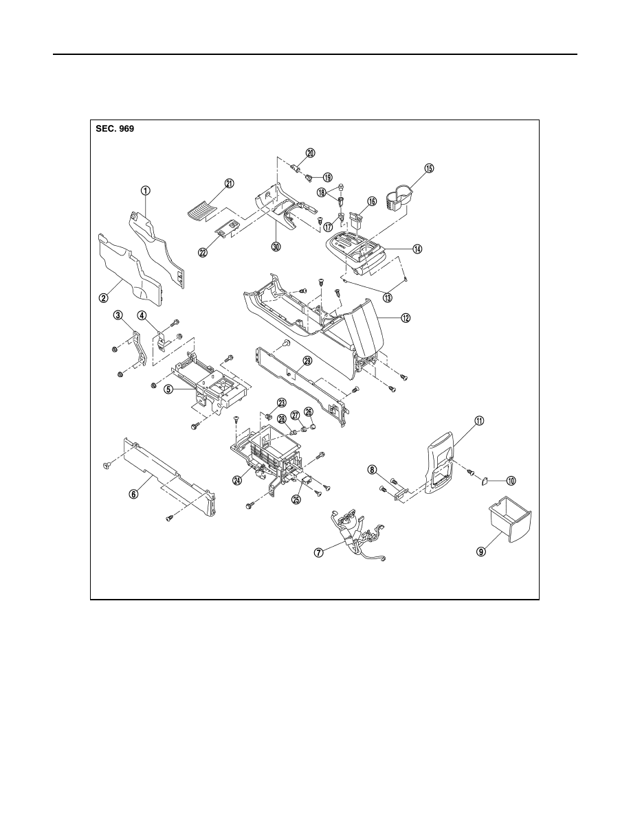
Exploded View
INFOID:0000000007542489
1.
Instrument lower cover RH
2.
Instrument lower cover LH
3.
Instrument stay LH
4.
Front console bracket
5.
Console reinforcement
6.
Lower console finisher LH
7.
Console harness
8.
Inside key antenna
9.
Rear console pocket
10. Console mask
11.
Console rear finisher
12. Center console assembly
13. Socket and bulb
14. Console finisher assembly
15. Cup holder assembly
16. Ashtray
17. Cigarette lighter ring
18. Cigarette lighter complete
19. Socket knob
20. Socket inner case
21. Console mat
22. Console switch finisher
23. USB connector
24. Lower console assembly
25. Auxiliary input jacks
26. Socket knob
27. Socket ring
28. Socket inner case
29. Lower console finisher RH
30. Front console pocket
JMJIA4761ZZ
Revision: 2013 February
2012 MURANO