Nissan Murano Z51 (2011 year). Manual - part 61


  Index      Manuals     Nissan Murano Z51 (2011 year) - Service and Repair Manual


Search            copyright infringement  


Content      ..     59      60      61      62     ..


Nissan Murano Z51 (2011 year). Manual - part 61


PREPARATION

WT-5

< PREPARATION >

C

D

F

G

H

I

J

K

L

M

A

B

WT

N

O

P

PREPARATION

PREPARATION

Special Service Tool

INFOID:0000000006260266

The actual shapes of Kent-Moore tools may differ from those of special service tools illustrated here.

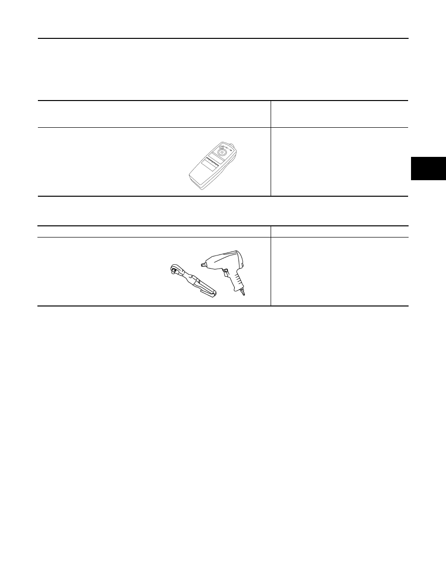
Commercial Service Tool

INFOID:0000000006260267

Tool number 
(Kent-Moore No.)
Tool name

Description


(J-45295)
Transmitter activation tool

ID registration

SEIA0462E

Tool name

Description

Power tool

Loosening bolts and nuts

PBIC0190E

Revision: 2011 November

2011 MURANO

WT-6

< SYSTEM DESCRIPTION >

COMPONENT PARTS

SYSTEM DESCRIPTION

COMPONENT PARTS

Component Parts Location

INFOID:0000000006260268

Component Description

INFOID:0000000006260269

BCM

INFOID:0000000006260270

The BCM reads the air pressure signal received by the tire pressure receiver, and controls the low tire pres-
sure warning lamp operation. It also has a judgment function to detect a system malfunction.

1.

Transmitter

2.

BCM

3.

Tire pressure receiver

A.

Wheel

B.

Behind of combination meter

C.

Instrument lower panel LH

D.

Low tire pressure warning lamp, infor-
mation display (in combination meter)

JSEIA0308ZZ

Component parts

Function

BCM (Body Control Module)

WT-6, "BCM"

.

Transmitter

WT-7, "Transmitter"

.

Tire pressure receiver

WT-7, "Tire Pressure Receiver"

.

Turn signal lamp

ID registration of each wheel has been completed, turn signal lamp flashes.

Combination meter

Transmits the vehicle speed signal via CAN communication to BCM.

Receives the following signals via CAN communication to BCM.
• Low tire pressure warning lamp signal
• TPMS warning lamp signal

Low tire pressure warning lamp

WT-8, "System Description"

Information display

WT-7, "Information Display"

Revision: 2011 November

2011 MURANO

COMPONENT PARTS

WT-7

< SYSTEM DESCRIPTION >

C

D

F

G

H

I

J

K

L

M

A

B

WT

N

O

P

Transmitter

INFOID:0000000006260271

The transmitter integrated with a valve is installed on a wheel, and transmits a detected air pressure signal by
radio wave. 

Tire Pressure Receiver

INFOID:0000000006260272

The tire pressure receiver receives the air pressure signal transmitted by the transmitter in each wheel.

Information Display

INFOID:0000000006598169

The vehicle information display is shown when a low tire pressure warning lamp signal is transmitted from
BCM to combination meter via CAN communication.

Condition

Vehicle information display

Ignition switch OFF

Non-indication

Low tire pressure

Indication

Revision: 2011 November

2011 MURANO

WT-8

< SYSTEM DESCRIPTION >

TPMS

TPMS

System Description

INFOID:0000000006598474

During driving, the TPMS (Tire Pressure Monitoring System) receives the signal transmitted from transmitter
installed in each wheel. The BCM (Body Control Module) of this system has pressure judgment and trouble
diagnosis functions. When the tire pressure monitoring system detects low inflation pressure or another
unusual symptom, the low tire pressure warning lamps in the combination meter comes on.

SYSTEM DIAGRAM

INPUT/OUTPUT SIGNAL

The signal transmission/reception between units via a communication line is mainly as listed in the following
table.

LOW TIRE PRESSURE WARNING LAMP INDICATION CONDITION

Uses CAN communication from the BCM to illuminate the low tire pressure warning lamp on the combination
meter.

JSEIA0157GB

Component parts

Signal item

BCM

Transmits the following signals via CAN communication to combination meter.
• Low tire pressure warning lamp signal

Combination meter

Transmits the vehicle speed signal via CAN communication to BCM.

Condition

Low tire pressure warning lamp

Ignition switch OFF

OFF

Ignition switch ON
(system normal)

Warning lamp turns on for 1second, then turns off.

Low tire pressure

ON

Transmitter ID not registered in BCM

Tire pressure monitoring system malfunction
(Other diagnostic item)

Warning lamp blinks 1 min, then turns on.

Tire pressure sensor is in OFF state

Blink

(Blinking pattern depends on the positions of non-operational tire pressure sensors.)

Revision: 2011 November

2011 MURANO

DIAGNOSIS SYSTEM (BCM)

WT-9

< SYSTEM DESCRIPTION >

C

D

F

G

H

I

J

K

L

M

A

B

WT

N

O

P

DIAGNOSIS SYSTEM (BCM)

COMMON ITEM

COMMON ITEM : CONSULT-III Function (BCM - COMMON ITEM)

INFOID:0000000006260278

APPLICATION ITEM

CONSULT-III performs the following functions via CAN communication with BCM.

SYSTEM APPLICATION

BCM can perform the following functions for each system.
NOTE:
It can perform the diagnosis modes except the following for all sub system selection items.

×

: Applicable item

NOTE:

• *1: At models with Intelligent Key system this item is displayed, but is not used.

• *2: At models with rain sensor this mode is displayed, but is not used.

Diagnosis mode

Function Description

Work Support

Changes the setting for each system function.

Self Diagnostic Result

Displays the diagnosis results judged by BCM.

CAN Diag Support Monitor

Monitors the reception status of CAN communication viewed from BCM. Refer to CONSULT-III opera-
tion manual.

Data Monitor

The BCM input/output signals are displayed.

Active Test

The signals used to activate each device are forcibly supplied from BCM.

Ecu Identification

The BCM part number is displayed.

Configuration

• Read and save the vehicle specification.
• Write the vehicle specification when replacing BCM.

System

Sub system selection item

Diagnosis mode

Work Support

Data Monitor

Active Test

Door lock

DOOR LOCK

×

×

×

Rear window defogger

REAR DEFOGGER

×

×

Warning chime

BUZZER

×

×

Interior room lamp timer

INT LAMP

×

×

×

Remote keyless entry system

MULTI REMOTE ENT*

1

×

×

×

Exterior lamp

HEAD LAMP

×

×

×

Wiper and washer

WIPER

×

*

2

×

×

Turn signal and hazard warning lamps

FLASHER

×

×

×

AIR CONDITONER*

3

• Intelligent Key system
• Engine start system

INTELLIGENT KEY

×

×

×

Combination switch

COMB SW

×

Body control system

BCM

×

NVIS - NATS

IMMU

×

×

Interior room lamp battery saver

BATTERY SAVER

×

×

×

Back door opener system

TRUNK

×

×

Vehicle security system

THEFT ALM

×

×

×

RAP system

RETAINED PWR

×

Signal buffer system

SIGNAL BUFFER

×

×

TPMS

TPMS (AIR PRESSURE MONITOR)

×

×

×

Revision: 2011 November

2011 MURANO

WT-10

< SYSTEM DESCRIPTION >

DIAGNOSIS SYSTEM (BCM)

• *3: This item is displayed, but is not used. 

FREEZE FRAME DATA (FFD)

The BCM records the following vehicle condition at the time a particular DTC is detected, and displays on
CONSULT-III.

AIR PRESSURE MONITOR

AIR PRESSURE MONITOR : CONSULT-III Function (BCM - AIR PRESSURE MONI-
TOR)

INFOID:0000000006598663

APPLICATION ITEMS

CONSULT-III performs the following functions via CAN communication with BCM.

CONSULT screen item

Indication/Unit

Description

Vehicle Speed

km/h

Vehicle speed of the moment a particular DTC is detected

Odo/Trip Meter

km

Total mileage (Odometer value) of the moment a particular DTC is detected

Vehicle Condition

SLEEP>LOCK

Power position status of 
the moment a particular 
DTC is detected

While turning BCM status from low power consumption mode to 
normal mode (Power supply position is “LOCK”)

SLEEP>OFF

While turning BCM status from low power consumption mode to 
normal mode (Power supply position is “OFF”.)

LOCK>ACC

While turning power supply position from “LOCK” to “ACC”

ACC>ON

While turning power supply position from “ACC” to “IGN”

RUN>ACC

While turning power supply position from “RUN” to “ACC” (Vehicle 
is stopping and selector lever is except P position.)

CRANK>RUN

While turning power supply position from “CRANKING” to “RUN” 
(From cranking up the engine to run it)

RUN>URGENT

While turning power supply position from “RUN“ to “ACC” (Emer-
gency stop operation)

ACC>OFF

While turning power supply position from “ACC” to “OFF”

OFF>LOCK

While turning power supply position from “OFF” to “LOCK”

OFF>ACC

While turning power supply position from “OFF” to “ACC”

ON>CRANK

While turning power supply position from “IGN” to “CRANKING”

OFF>SLEEP

While turning BCM status from normal mode (Power supply posi-
tion is “OFF”.) to low power consumption mode

LOCK>SLEEP

While turning BCM status from normal mode (Power supply posi-
tion is “LOCK”.) to low power consumption mode

LOCK

Power supply position is “LOCK” (Ignition switch OFF with steer-
ing is locked.)

OFF

Power supply position is “OFF” (Ignition switch OFF with steering 
is unlocked.)

ACC

Power supply position is “ACC” (Ignition switch ACC)

ON

Power supply position is “IGN” (Ignition switch ON with engine 
stopped)

ENGINE RUN

Power supply position is “RUN” (Ignition switch ON with engine 
running)

CRANKING

Power supply position is “CRANKING” (At engine cranking)

IGN Counter

0 - 39

The number of times that ignition switch is turned ON after DTC is detected
• The number is 0 when a malfunction is detected now.
• The number increases like 1 

 2 

 3...38 

 39 after returning to the normal condition 

whenever ignition switch OFF 

 ON.

• The number is fixed to 39 until the self-diagnosis results are erased if it is over 39.

Revision: 2011 November

2011 MURANO

DIAGNOSIS SYSTEM (BCM)

WT-11

< SYSTEM DESCRIPTION >

C

D

F

G

H

I

J

K

L

M

A

B

WT

N

O

P

SELF DIAGNOSTIC RESULT

Refer to 

BCS-78, "DTC Index"

.

When “CRNT” is displayed on self-diagnosis result,

• The system is presently malfunctioning.

When “PAST” is displayed on self-diagnosis result,

• System malfunction in the past is detected, but the system is presently normal.

DATA MONITOR MODE

Screen of data monitor mode is displayed.
NOTE:
When malfunction is detected, CONSULT-III perform REAL-TIME DIAGNOSIS.
Also, any malfunction detected while in this mode will be displayed at real time.

NOTE:
Before performing the self-diagnosis, be sure to register the ID, or erase the actual malfunction location may
be different from that displayed on CONSULT-III.

ACTIVE TEST MODE

NOTE:
Before performing the self-diagnosis, be sure to register the ID, or erase the actual malfunction may be differ-
ent from that displayed on CONSULT-III.

TEST ITEM LIST

WORK SUPPORT MODE

Diagnosis mode

Function Description

Self Diagnostic Result

Displays the diagnosis results judged by BCM.

Data Monitor

The BCM input/output signals are displayed.

Active Test

The signals used to activate each device are forcibly supplied from BCM.

Work Support

Components can be quickly and accurately adjusted.

Monitor item (Unit)

Remark

AIR PRESS FL (kPa//kg/cm

2

/Psi)

Tire pressure

AIR PRESS FR (kPa//kg/cm

2

/Psi)

AIR PRESS RR (kPa//kg/cm

2

/Psi) 

AIR PRESS RL (kPa//kg/cm

2

/Psi)

ID REGST FL1 (Green/Red)

Registration ID

ID REGST FR1 (Green/Red)

ID REGST RR1 (Green/Red)

ID REGST RL1 (Green/Red)

WARNING LAMP (On/Off)

Low tire pressure warning lamp

BUZZER (On/Off)

NOTE:
This item is displayed, but cannot be use this item.

Test item

Content

WARNING LAMP

This test is able to check to check that the low tire pressure warning lamp turns on.

ID REGIST WARNING

This test is able to check to check that the low tire pressure warning lamp turns on.

FLASHER

This test is able to check to check that each turn signal lamp turns on.

HORN

This test is able to check to check that the horn sounds.

Revision: 2011 November

2011 MURANO

WT-12

< SYSTEM DESCRIPTION >

DIAGNOSIS SYSTEM (BCM)

Item

Description

ID READ

Registered tire pressure sensor ID can be displayed.

ID REGIST

Tire pressure sensor ID can be registered.

Revision: 2011 November

2011 MURANO

BCM

WT-13

< ECU DIAGNOSIS INFORMATION >

C

D

F

G

H

I

J

K

L

M

A

B

WT

N

O

P

ECU DIAGNOSIS INFORMATION

BCM

List of ECU Reference

INFOID:0000000006260281

ECU

Reference

BCM

BCS-47, "Reference Value"

BCS-76, "Fail-safe"

BCS-78, "DTC Inspection Priority Chart"

BCS-78, "DTC Index"

Revision: 2011 November

2011 MURANO

WT-14

< WIRING DIAGRAM >

TIRE PRESSURE MONITORING SYSTEM

WIRING DIAGRAM

TIRE PRESSURE MONITORING SYSTEM

Wiring Diagram

INFOID:0000000006260282

JCEWM0254GB

Revision: 2011 November

2011 MURANO

TIRE PRESSURE MONITORING SYSTEM

WT-15

< WIRING DIAGRAM >

C

D

F

G

H

I

J

K

L

M

A

B

WT

N

O

P

JCEWM0255GB

Revision: 2011 November

2011 MURANO

WT-16

< WIRING DIAGRAM >

TIRE PRESSURE MONITORING SYSTEM

JCEWM0256GB

Revision: 2011 November

2011 MURANO

DIAGNOSIS AND REPAIR WORK FLOW

WT-17

< BASIC INSPECTION >

C

D

F

G

H

I

J

K

L

M

A

B

WT

N

O

P

BASIC INSPECTION

DIAGNOSIS AND REPAIR WORK FLOW

Work Flow 

INFOID:0000000006260283

DETAILED FLOW

1.

COLLECT THE INFORMATION FROM THE CUSTOMER

It is also important to clarify customer concerns before starting the inspection. Reproduce the symptom, and
understand it fully. Interview the customer about the concerns carefully. In some cases, it is necessary to
check the symptoms by driving the vehicle with the customer.

CAUTION:

Customers are not professionals. Never assume“maybe the customer means...” or “maybe the cus-
tomer mentioned this symptom.

>> GO TO 2.

2.

BASIC INSPECTION

1.

Turn the ignition switch ON.

CAUTION:

Never start the engine.

2.

Check the tire pressure for all wheels and adjust to the specified value. Refer to 

WT-52, "Tire Air Pres-

sure"

Is the inspection result normal?

YES

>> GO TO 3.

NO

>> Inspect or repair the tires or wheels.

3.

CHECK LOW TIRE PRESSURE WARNING LAMP

Check low tire pressure warning lamp display.
Does not low tire pressure warning lamp turn OFF?

YES

>> GO TO 4.

NO

>> INSPECTION END

4.

CRUISE TEST

Start the engine and drive the vehicle.

>> GO TO 5.

5.

PERFORM SELF-DIAGNOSIS

With CONSULT-III

Perform “SELF-DIAG RESULTS” in “AIR PRESSURE MONITOR” of “BCM”.

Is any DTC detected?

YES

>> GO TO 7.

NO

>> GO TO 6.

6.

CHECK SYMPTOM

Perform trouble diagnosis for the applicable symptom. Refer to 

WT-36, "Symptom Table"

Is the cause of the malfunction detected?

YES

>> GO TO 8.

NO

>> GO TO 10.

7.

CIRCUIT DIAGNOSIS

Inspect the malfunctioning system indicated by the DTC code that is detected during self-diagnosis. Refer to

BCS-78, "DTC Index"

>> GO TO 8.

Revision: 2011 November

2011 MURANO

WT-18

< BASIC INSPECTION >

DIAGNOSIS AND REPAIR WORK FLOW

8.

REPAIR WORK

Repair or replace the malfunctioning part.

>> GO TO 9.

9.

PERFORM SELF-DIAGNOSIS

1.

Select “SELF-DIAG RESULTS” in “AIR PRESSURE MONITOR” of “BCM”.

2.

Touch “ERASE” on CONSULT-III screen to erase memory.

3.

Drive the vehicle.

4.

Perform “SELF-DIAG RESULTS” in “AIR PRESSURE MONITOR” of “BCM”.

Is any DTC detected?

YES

>> GO TO 7.

NO

>> GO TO 10.

10.

FINAL CHECK

1.

Perform a cruise test.

2.

Check that the low tire pressure warning lamp turn OFF.

Dose the tire pressure warning lamp turn OFF?

YES

>> INSPECTION END

NO

>> GO TO 2.

Revision: 2011 November

2011 MURANO

ADDITIONAL SERVICE WHEN REPLACING BCM

WT-19

< BASIC INSPECTION >

C

D

F

G

H

I

J

K

L

M

A

B

WT

N

O

P

ADDITIONAL SERVICE WHEN REPLACING BCM

Description

INFOID:0000000006598664

When replacing BCM, transmitter ID registration is required.

Work Procedure

INFOID:0000000006598665

1.

PERFORM TRANSMITTER ID REGISTRATION

Perform transmitter ID registration.

>> Refer to 

WT-21, "Work Procedure"

.

Revision: 2011 November

2011 MURANO

WT-20

< BASIC INSPECTION >

TRANSMITTER WAKE UP OPERATION

TRANSMITTER WAKE UP OPERATION

Description

INFOID:0000000006598666

This procedure must be done after replacement of a transmitter, BCM, or rotation of wheels.

Work Procedure

INFOID:0000000006598667

1.

TRANSMITTER WAKE-UP PROCEDURE

1.

Turn the ignition switch ON.

CAUTION:

Never start the engine.
NOTE:
The position of an inactive transmitter can be identified by checking the blinking timing of the low tire pres-
sure warning lamp.

2.

Contact the transmitter activation tool (J-45295) (1) to the side of
the tire at the location to the transmitter.

3.

Press and hold the activation tool button while pushing the tool
to the tire surface. (approximately for 5 seconds)

CAUTION:

Perform the wake-up procedure starting from the vehicle
front left wheel, then repeat the procedure in the order of
the front right wheel, rear right wheel, and rear left wheel.

4.

Check that the turn signal lamps blink twice when the transmitter
wake-up procedure for all wheels is completed.

5.

Check that the low tire pressure warning lamp turns OFF, after
the transmitter wake-up procedure is completed for all wheels
and turns OFF.

Is the transmitter wake-up procedure completed?

YES

>> Perform the transmitter ID registration procedure. Refer to 

WT-21, "Work Procedure"

NO

>> Perform trouble diagnosis for the transmitter. Refer to 

WT-25, "Diagnosis Procedure"

JPEIC0089GB

NNEIC0020ZZ

Revision: 2011 November

2011 MURANO


Content      ..     59      60      61      62     ..