Nissan Murano Z51 (2011 year). Manual - part 37
GW-22
< REMOVAL AND INSTALLATION >
FRONT REGULATOR
Disassembly and Assembly
INFOID:0000000006258389
DISASSEMBLY
1.
Remove the power window motor from the module assembly.
2.
Remove the regulator assembly mounting bolts, then remove the regulator assembly from module base.
ASSEMBLY
Assemble in the reverse order of disassembly.
Inspection and Adjustment
INFOID:0000000006258390
Inspection after Removal
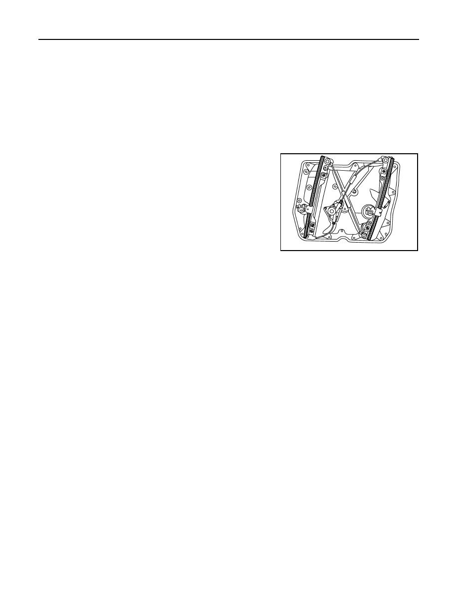
Check the regulator assembly for the following items. Replace or
grease it if a malfunction is detected.
• Wire wear
• Regulator deformation
The shadow area in the figure show the application points of the
multi-purpose grease.
SYSTEM INITIALIZATION
Initialize the system if any of the following work has been done.
• Electric power supply to power window switch or motor is interrupted by blown fuse or disconnecting battery
cable, etc.
• Removal and installation of the regulator assembly.
• Removal and installation of the motor from the regulator assembly.
• Removal and installation of the harness connector of the power window switch.
• Removal and installation of the door glass.
• Removal and installation of the front door glass run.
• Disconnection and connection of the minus terminal of battery.
Initialization
Follow the steps below after installing each component to the vehicle.
1.
Disconnect the minus terminal of battery or disconnect power window switch harness connector tempo-
rarily. Then reconnect after at least 1 minute.
2.
Turn ignition switch ON.
3.
Operate power window switch to fully open the window.
4.
Draw fully the power window switch in the up direction (auto close position) and hold. Continue holding
the switch even when window is completely closed and then release after more than 3 seconds.
5.
Inspect the anti-pinch system function.
NOTE:
Initialization may be cancelled with continuous opening and closing operation. In this case, initialize the
system.
INSPECT THE FUNCTION OF THE ANTI-PINCH SYSTEM
1.
Fully open the door glass.
2.
Place a wooden piece (wooden hammer handle, etc.) at near fully closed position.
3.
Perform fully closing operation with auto up switch.
• Check that the glass reverses without pinching the wooden piece, is lowered approximately 150 mm (5.906
in) or for more than 3 seconds and then stops.
• The glass should not be raised with power window main switch operated while it is reversing or lowering.
CAUTION:
• Be careful not to be pinched.
• Check that the auto up function is normal before the inspection following the system initialization.
JMKIA1787ZZ
Revision: 2011 November
2011 MURANO