Nissan Murano Z51 (2011 year). Manual - part 34
PRECAUTIONS
GI-29
< PRECAUTION >
C
D
E
F
G
H
I
J
K
L
M
B
GI
N
O
P
• Dispose of the used xenon bulb after packing it in thick vinyl without breaking it.
• Never wipe out dirt and contamination with organic solvent (thinner, gasoline, etc.).
FOR USA AND CANADA : Precaution for Procedure without Cowl Top Cover
INFOID:0000000007545221
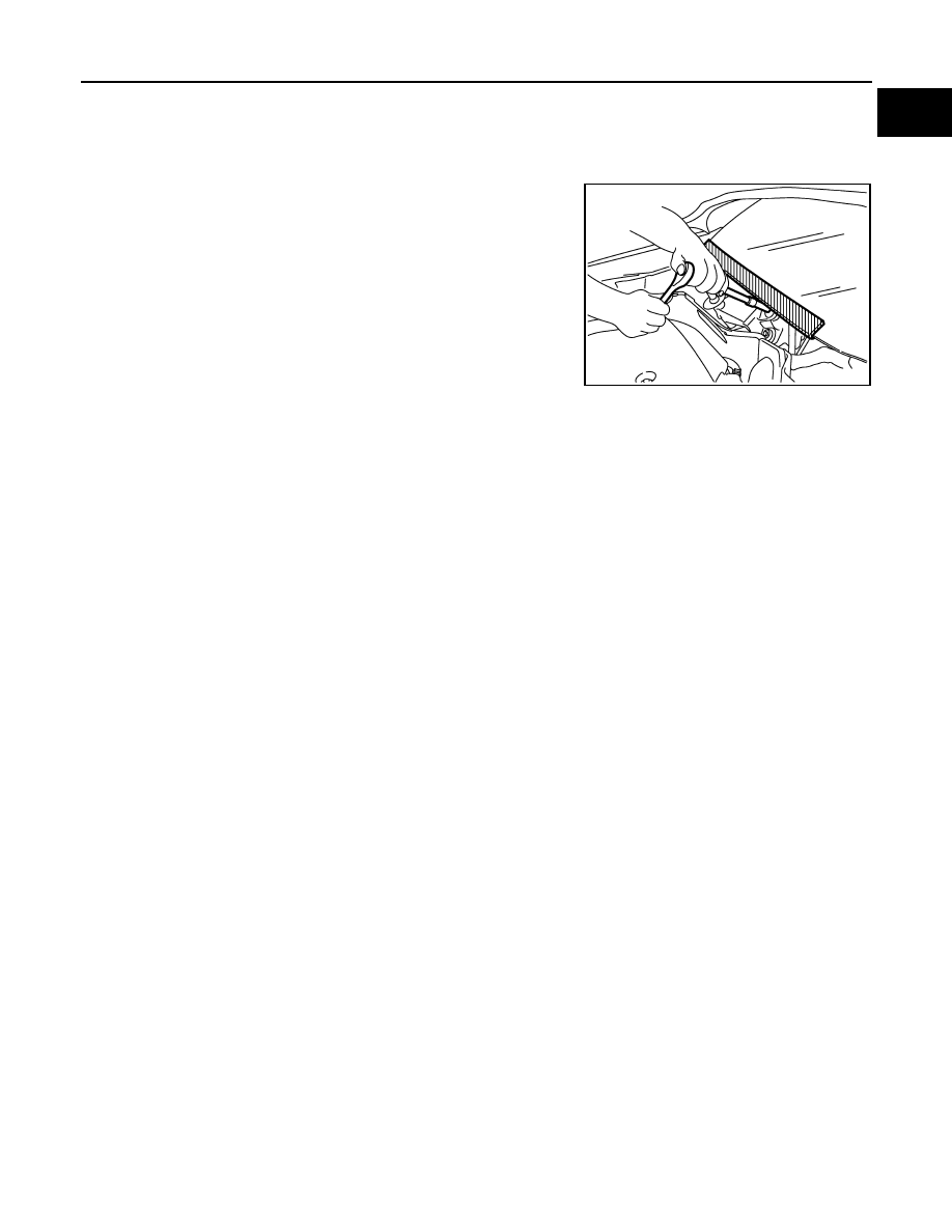
When performing the procedure after removing cowl top cover, cover
the lower end of windshield with urethane, etc to prevent damage to
windshield.
FOR USA AND CANADA : Cautions in Removing Battery Terminal and AV Control Unit
(Models with AV Control Unit)
INFOID:0000000007793347
CAUTION:
Remove battery terminal and AV control unit after a lapse of 30 seconds or more after turning the igni-
tion switch OFF.
NOTE:
After the ignition switch is turned OFF, the AV control unit continues operating for approximately 30 seconds.
Therefore, data corruption may occur if battery voltage is cut off within 30 seconds.
FOR MEXICO
FOR MEXICO : Precaution for Supplemental Restraint System (SRS) "AIR BAG" and
"SEAT BELT PRE-TENSIONER"
INFOID:0000000007545222
The Supplemental Restraint System such as “AIR BAG” and “SEAT BELT PRE-TENSIONER”, used along
with a front seat belt, helps to reduce the risk or severity of injury to the driver and front passenger for certain
types of collision. Information necessary to service the system safely is included in the “SRS AIR BAG” and
“SEAT BELT” of this Service Manual.
WARNING:
Always observe the following items for preventing accidental activation.
• To avoid rendering the SRS inoperative, which could increase the risk of personal injury or death in
the event of a collision that would result in air bag inflation, all maintenance must be performed by
an authorized NISSAN/INFINITI dealer.
• Improper maintenance, including incorrect removal and installation of the SRS, can lead to personal
injury caused by unintentional activation of the system. For removal of Spiral Cable and Air Bag
Module, see “SRS AIR BAG”.
• Never use electrical test equipment on any circuit related to the SRS unless instructed to in this Ser-
vice Manual. SRS wiring harnesses can be identified by yellow and/or orange harnesses or harness
connectors.
PRECAUTIONS WHEN USING POWER TOOLS (AIR OR ELECTRIC) AND HAMMERS
WARNING:
Always observe the following items for preventing accidental activation.
• When working near the Air Bag Diagnosis Sensor Unit or other Air Bag System sensors with the
ignition ON or engine running, never use air or electric power tools or strike near the sensor(s) with
a hammer. Heavy vibration could activate the sensor(s) and deploy the air bag(s), possibly causing
serious injury.
• When using air or electric power tools or hammers, always switch the ignition OFF, disconnect the
battery, and wait at least 3 minutes before performing any service.
FOR MEXICO : Precautions For Xenon Headlamp Service
INFOID:0000000007545223
WARNING:
PIIB3706J
Revision: 2013 February
2012 MURANO