Nissan Murano Z50 (2007 year). Manual - part 191


  Index      Manuals     Nissan Murano Z50 (2007 year) - Service and Repair Manual


Search            copyright infringement  


Content      ..     189      190      191      192     ..


Nissan Murano Z50 (2007 year). Manual - part 191


SERVICE DATA AND SPECIFICATIONS (SDS)

TF-71

C

E

F

G

H

I

J

K

L

M

A

B

TF

Revision: 2006 July

2007 Murano

SERVICE DATA AND SPECIFICATIONS (SDS)

PFP:00030

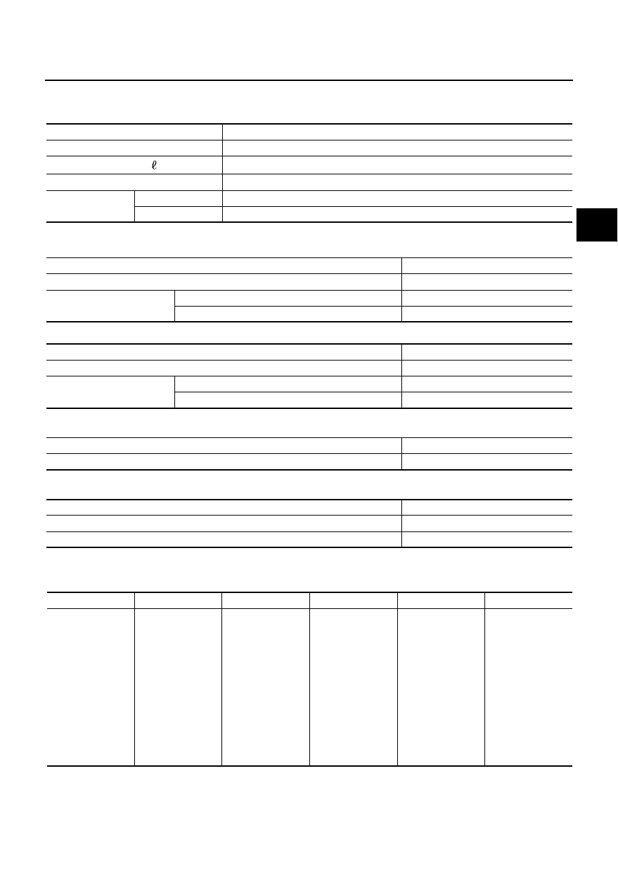
General Specifications

NDS00082

Inspection and Adjustment

NDS00083

PRELOAD TORQUE BEFORE DISASSEMBLY

PRELOAD TORQUE AFTER DISASSEMBLY AND REASSEMBLY 

BACKLASH

Unit: mm (in)

COMPANION FLANGE RUNOUT

Unit: mm (in)

SELECTIVE PARTS
Gear Ring Bearing Adjusting Shim (Transfer Case Side)

Unit: mm (in)

*: Always check with the Parts Department for the latest parts information.

Applied model

VQ35DE

Transfer model

TY20A

Oil capacity (Approx.)

 (US pt, lmp pt)

0.31 (5/8, 1/2)

Gear ratio

0.404

Number of teeth 

Drive pinion

17

Drive gear

42

Item

Specification [N·m (kg-m, in-lb)]

Pinion bearing (P

1

 )

0.10 - 0.39 (0.01 - 0.04, 1 - 3)

Gear ring bearing to pinion 
bearing (Total preload)

With all oil seals

P

1

  + 0.16 - 0.22 (0.016 - 0.023, 1.4 - 1.9)

Without transfer case oil seal and adapter case oil seal

P

 + 0.06 - 0.12 (0.006 - 0.013, 0.6 - 1.1)

Item

Specification [N·m (kg-m, in-lb)]

Pinion bearing (P’

1

 )

0.40 - 0.78 (0.04 - 0.08, 4 - 6)

Gear ring bearing to pinion 
bearing (Total preload)

With all oil seals

P’

1

  + 0.45 - 0.47 (0.045 - 0.048, 3.9 - 4.1)

Without transfer case oil seal and adapter case oil seal

P’

1

  + 0.35 - 0.37 (0.035 - 0.038, 3.1 - 3.2)

Item

Standard 

Drive gear to drive pinion gear

0.13 - 0.19 (0.0051 - 0.0075)

Item

Runout limit

Companion flange face

 0.1 (0.004)

Inner side of the companion flange

 0.1 (0.004)

Thickness Part 

number*

Thickness Part 

number*

Thickness Part 

number*

0.80 (0.0315)
0.83 (0.0327)
0.86 (0.0339)
0.89 (0.0350)
0.92 (0.0362)
0.95 (0.0374)
0.98 (0.0386)
1.01 (0.0398)
1.04 (0.0409)
1.07 (0.0421)
1.10 (0.0433)
1.13 (0.0445)
1.16 (0.0457)
1.19 (0.0469)

33147 AD300
33147 AD301
33147 AD302
33147 AD303
33147 AD304
33147 AD305
33147 AD306
33147 AD307
33147 AD308
33147 AD309
33147 AD310
33147 AD311
33147 AD312
33147 AD313

1.22 (0.0480)
1.25 (0.0492)
1.28 (0.0504)
1.31 (0.0516)
1.34 (0.0528)
1.37 (0.0539)
1.40 (0.0551)
1.43 (0.0563)
1.46 (0.0575)
1.49 (0.0587)
1.52 (0.0598)
1.55 (0.0610)
1.58 (0.0622)
1.61 (0.0634)

33147 AD314
33147 AD315
33147 AD316
33147 AD317
33147 AD318
33147 AD319
33147 AD320
33147 AD321
33147 AD322
33147 AD323
33147 AD324
33147 AD360
33147 AD361
33147 AD362

1.64 (0.0646)
1.67 (0.0657)
1.70 (0.0669)
1.73 (0.0681)
1.76 (0.0693)
1.79 (0.0705)
1.82 (0.0717)
1.85 (0.0728)
1.88 (0.0740)
1.91 (0.0752)
1.94 (0.0764)
1.97 (0.0776)
2.00 (0.0787)
2.03 (0.0799)

33147 AD363
33147 AD364
33147 AD365
33147 AD366
33147 AD367
33147 AD368
33147 AD369
33147 AD370
33147 AD371
33147 AD372
33147 AD373
33147 AD374
33147 AD375
33147 AD376

TF-72

SERVICE DATA AND SPECIFICATIONS (SDS)

Revision: 2006 July

2007 Murano

Gear Ring Bearing Adjusting Shim (Adapter Case Side)

Unit: mm (in)

*: Always check with the Parts Department for the latest parts information.

Pinion Sleeve Shim

Unit: mm (in)

*: Always check with the Parts Department for the latest parts information.

Thickness 

Part number*

Thickness 

Part number*

Thickness 

Part number*

0.80 (0.0315)
0.83 (0.0327)
0.86 (0.0339)
0.89 (0.0350)
0.92 (0.0362)
0.95 (0.0374)
0.98 (0.0386)
1.01 (0.0398)
1.04 (0.0409)
1.07 (0.0421)
1.10 (0.0433)
1.13 (0.0445)
1.16 (0.0457)
1.19 (0.0469)
1.22 (0.0480)

33147 5V200
33147 5V201
33147 5V202
33147 5V203
33147 5V204
33147 5V205
33147 5V206
33147 5V207
33147 5V208
33147 5V209
33147 5V210
33147 5V211
33147 5V212
33147 5V213
33147 5V214

1.25 (0.0492)
1.28 (0.0504)
1.31 (0.0516)
1.34 (0.0528)
1.37 (0.0539)
1.40 (0.0551)
1.43 (0.0563)
1.46 (0.0575)
1.49 (0.0587)
1.52 (0.0598)
1.55 (0.0610)
1.58 (0.0622)
1.61 (0.0634)
1.64 (0.0646)
1.67 (0.0657)

33147 5V215
33147 5V216
33147 5V217
33123 5V218
33123 5V219
33123 5V220
33123 5V221
33123 5V222
33123 5V223
33123 5V224
33123 5V260
33123 5V261
33123 5V262
33123 5V263
33123 5V264

1.70 (0.0669)
1.73 (0.0681)
1.76 (0.0693)
1.79 (0.0705)
1.82 (0.0717)
1.85 (0.0728)
1.88 (0.0740)
1.91 (0.0752)
1.94 (0.0764)
1.97 (0.0776)
2.00 (0.0787)
2.03 (0.0799)

2.06 (0.0811)
2.09 (0.0811)

33123 5V265
33123 5V266
33123 5V267
33123 5V268
33123 5V269
33123 5V270
33123 5V271
33123 5V272
33123 5V273
33123 5V274
33123 5V275
33123 5V276
33123 5V277
33123 5V278

Thickness

Part number*

Thickness

Part number*

Thickness

Part number*

0.77 (0.0303)
0.80 (0.0315)
0.83 (0.0327)
0.86 (0.0339)
0.89 (0.0350)
0.92 (0.0362)
0.95 (0.0374)

33155 5V214
33155 5V200
33155 5V201
33155 5V202
33155 5V203
33155 5V204
33155 5V205

0.98 (0.0386)
1.01 (0.0398)
1.04 (0.0409)
1.07 (0.0421)
1.10 (0.0433)
1.13 (0.0445)
1.16 (0.0457)

33155 5V206
33155 5V207
33155 5V208
33155 5V209
33155 5V210

33155 5V211

33155 5V212

1.19 (0.0469)
1.22 (0.0480)
1.25 (0.0492)
1.28 (0.0504)
1.31 (0.0516)
1.34 (0.0528)

33155 5V213
33155 5V215
33155 5V216
33155 5V217
33155 5V218
33155 5V219

WT-1

ROAD WHEELS & TIRES

E  SUSPENSION

CONTENTS

C

D

F

G

H

I

J

K

L

M

SECTION 

A

B

WT

Revision: 2006 July

2007 Murano

ROAD WHEELS & TIRES

INDEX FOR DTC  ........................................................ 3

DTC No. Index  ......................................................... 3

PRECAUTIONS .......................................................... 4

Precautions for Supplemental Restraint System 
(SRS) “AIR BAG” and “SEAT BELT PRE-TEN-
SIONER” .................................................................. 4
Precautions .............................................................. 4
Service Notice or Precautions  .................................. 5

PREPARATION ........................................................... 6

Special Service Tools  ............................................... 6
Commercial Service Tools ........................................ 6

NOISE, VIBRATION AND HARSHNESS (NVH) 
TROUBLESHOOTING ................................................ 7

NVH Troubleshooting Chart  ..................................... 7

TIRE PRESSURE MONITORING SYSTEM  ............... 8

System Description  .................................................. 8

DESCRIPTION ...................................................... 8
TRANSMITTER ..................................................... 8
REMOTE KEYLESS ENTRY RECEIVER  ............. 8
BCM (BODY CONTROL MODULE) ...................... 8
LOW TIRE PRESSURE WARNING LAMP  ........... 9
VEHICLE INFORMATION DISPLAY  ..................... 9
TIRE PRESSURE WARNING CHECK SWITCH 

..... 9

System Diagram ..................................................... 10

COMPONENTS FUNCTION DESCRIPTION  ..... 10

Can Communication ............................................... 10

SYSTEM DESCRIPTION  .................................... 10

TROUBLE DIAGNOSES  ...........................................11

How to Perform Trouble Diagnosis  .........................11

BASIC CONCEPT  ................................................11
INTRODUCTION ..................................................11
WORK FLOW ...................................................... 12

Component Parts Location ..................................... 13
Circuit Diagram  ...................................................... 14
Wiring Diagram — T/WARN —  .............................. 15
BCM Input/Output Signal Reference Values  .......... 18

BCM INSPECTION TABLE (FOR LOW TIRE 
PRESSURE WARNING SYSTEM)  ..................... 18

CONSULT-II Function (BCM)  ................................. 20

CONSULT-II MAIN FUNCTION ........................... 20

CONSULT-II SETTING PROCEDURE  ................ 20
WORK SUPPORT MODE  ................................... 20
SELF-DIAG RESULT MODE ............................... 22
DATA MONITOR MODE ...................................... 23
ACTIVE TEST MODE  ......................................... 24

Self-Diagnostic Procedure ...................................... 24

SELF-DIAGNOSTIC PROCEDURE (WITH 
CONSULT-II) ....................................................... 24
SELF-DIAGNOSTIC PROCEDURE (WITHOUT 
CONSULT-II) ....................................................... 24
ERASE SELF-DIAGNOSIS  ................................. 26

ID Registration Procedure  ...................................... 26

ID REGISTRATION WITH TRANSMITTER 
ACTIVATION TOOL  ............................................ 26
ID REGISTRATION WITHOUT TRANSMITTER 
ACTIVATION TOOL  ............................................ 27

Transmitter Wake Up Operation  ............................. 28

WITH ACTIVATION TOOL  .................................. 28

Trouble Diagnosis Chart for Symptoms .................. 28
Low Tire Pressure Warning Lamp Symptom Chart ... 29
Inspections Before Trouble Diagnosis  .................... 31

DIAGNOSTIC PROCEDURE  .............................. 31

TROUBLE DIAGNOSIS FOR SYSTEM .................... 32

DTC C1708, C1709, C1710, C1711 [NO DATA] ..... 32

CONSULT-II REFERENCE VALUE IN DATA 
MONITOR MODE ................................................ 32
BCM TERMINALS AND REFERENCE VALUE ... 32
DIAGNOSTIC PROCEDURE  .............................. 33

DTC C1712, C1713, C1714, C1715 [CHECKSUM 
ERR] ....................................................................... 35

CONSULT-II REFERENCE VALUE IN DATA 
MONITOR MODE ................................................ 35
BCM TERMINALS AND REFERENCE VALUE ... 35
DIAGNOSTIC PROCEDURE  .............................. 36

DTC C1716, C1717, C1718, C1719 [PRESSDATA 
ERR] ....................................................................... 38

CONSULT-II REFERENCE VALUE IN DATA 
MONITOR MODE ................................................ 38
DIAGNOSTIC PROCEDURE  .............................. 38

DTC C1720, C1721, C1722, C1723 [CODE ERR] 

... 39

WT-2

Revision: 2006 July

2007 Murano

CONSULT-II REFERENCE VALUE IN DATA 
MONITOR MODE  ................................................ 39
BCM TERMINALS AND REFERENCE VALUE ... 39
DIAGNOSTIC PROCEDURE  .............................. 40

DTC C1724, C1725, C1726, C1727 [BATT VOLT 
LOW] ...................................................................... 42

CONSULT-II REFERENCE VALUE IN DATA 
MONITOR MODE  ................................................ 42
BCM TERMINALS AND REFERENCE VALUE ... 42
DIAGNOSTIC PROCEDURE  .............................. 43

DTC C1729 VHCL SPEED SIG ERR  ..................... 45

CONSULT-II REFERENCE VALUE IN DATA 
MONITOR MODE  ................................................ 45
DIAGNOSTIC PROCEDURE  .............................. 45

TROUBLE DIAGNOSIS FOR SYMPTOMS  .............. 46

Low Tire Pressure Warning Lamp Does Not Turn 
ON for Approx.1 Second When Ignition Switch Is 
Turned ON  .............................................................. 46

DIAGNOSTIC PROCEDURE  .............................. 46

Low Tire Pressure Warning Lamp Stays ON When 
Ignition Switch Is Turned ON  .................................. 46

DIAGNOSTIC PROCEDURE  .............................. 46

Low Tire Pressure warning Lamp Blinks When Igni-
tion Switch Is Turned ON  ........................................ 49

SYMPTOM: ..........................................................49
DIAGNOSTIC PROCEDURE ...............................49

Turn Signal Lamp Blinks When Ignition Switch Is 
Turned ON  ..............................................................50

DIAGNOSTIC PROCEDURE ...............................50

ID Registration Cannot Be Completed ....................50

DIAGNOSTIC PROCEDURE ...............................50

TRANSMITTER .........................................................51

Removal and Installation .........................................51

REMOVAL ............................................................51
INSTALLATION ....................................................51

ROAD WHEEL  ..........................................................53

Inspection ................................................................53

ALUMINUM WHEEL  ............................................53
STEEL WHEEL (FOR EMERGENCY USE)  ........53

ROAD WHEEL TIRE ASSEMBLY .............................54

Balancing Wheels (Bonding Weight Type) ..............54

REMOVAL ............................................................54
WHEEL BALANCE ADJUSTMENT  .....................54

Tire Rotation ............................................................55

SERVICE DATA AND SPECIFICATIONS (SDS)  ......56

Road Wheel  ............................................................56
Tire ..........................................................................56
Tightening Torque  ...................................................56

INDEX FOR DTC

WT-3

C

D

F

G

H

I

J

K

L

M

A

B

WT

Revision: 2006 July

2007 Murano

INDEX FOR DTC

PFP:00024

DTC No. Index

NES000FD

DTC

Items

 (CONSULT-II screen terms)

Reference page

C1704

LOW PRESSURE FL

WT-31

C1705

LOW PRESSURE FR

C1706

LOW PRESSURE RR

C1707

LOW PRESSURE RL

C1708

[NO DATA] FL

WT-32

C1709

[NO DATA] FR

C1710

[NO DATA] RR

C1711

[NO DATA] RL

C1712

[CHECKSUM ERR] FL

WT-35

C1713

[CHECKSUM ERR] FR

C1714

[CHECKSUM ERR] RR

C1715

[CHECKSUM ERR] RL

C1716

[PRESSDATA ERR] FL

WT-38

C1717

[PRESSDATA ERR] FR

C1718

[PRESSDATA ERR] RR

C1719

[PRESSDATA ERR] RL

C1720

[CODE ERR] FL

WT-39

C1721

[CODE ERR] FR

C1722

[CODE ERR] RR

C1723

[CODE ERR] RL

C1724

[BATT VOLT LOW] FL

WT-42

C1725

[BATT VOLT LOW] FR

C1726

[BATT VOLT LOW] RR

C1727

[BATT VOLT LOW] RL

C1729

VHCL SPEED SIG ERR

WT-45

WT-4

PRECAUTIONS

Revision: 2006 July

2007 Murano

PRECAUTIONS

PFP:00001

Precautions for Supplemental Restraint System (SRS) “AIR BAG” and “SEAT 
BELT PRE-TENSIONER”

NES000ES

The Supplemental Restraint System such as “AIR BAG” and “SEAT BELT PRE-TENSIONER”, used along
with a front seat belt, helps to reduce the risk or severity of injury to the driver and front passenger for certain
types of collision. This system includes seat belt switch inputs and dual stage front air bag modules. The SRS
system uses the seat belt switches to determine the front air bag deployment, and may only deploy one front
air bag, depending on the severity of a collision and whether the front occupants are belted or unbelted.
Information necessary to service the system safely is included in the SRS and SB section of this Service Man-
ual.

WARNING:

To avoid rendering the SRS inoperative, which could increase the risk of personal injury or death
in the event of a collision which would result in air bag inflation, all maintenance must be per-
formed by an authorized NISSAN/INFINITI dealer.

Improper maintenance, including incorrect removal and installation of the SRS, can lead to per-
sonal injury caused by unintentional activation of the system. For removal of Spiral Cable and Air
Bag Module, see the SRS section.

Do not use electrical test equipment on any circuit related to the SRS unless instructed to in this
Service Manual. SRS wiring harnesses can be identified by yellow and/or orange harnesses or
harness connectors.

Precautions

NES000L7

Before connecting or disconnecting the BCM harness con-
nector, turn ignition switch “OFF” and disconnect the bat-
tery cable from the negative terminal. Battery voltage is
applied to BCM even if ignition switch is turned “OFF”.

When connecting or disconnecting pin connectors into or
from BCM, take care not to damage pin terminals (bend or
break).
When connecting pin connectors make sure that there are
not any bends or breaks on BCM pin terminals.

Before replacing BCM, perform control unit input/output
signal inspection and make sure whether BCM functions
properly or not. Refer to 

WT-18, "BCM Input/Output Signal

Reference Values"

 .

SEF289H

SEF291H

SDIA1848E

PRECAUTIONS

WT-5

C

D

F

G

H

I

J

K

L

M

A

B

WT

Revision: 2006 July

2007 Murano

Service Notice or Precautions

NES000L8

Low tire pressure warning lamp flashes 1min, then turns ON when occurring any malfunction except low
tire pressure. Delete the memory with CONSULT-II, or register the ID to turn low tire pressure warning
lamp OFF. Refer to 

WT-26, "ERASE SELF-DIAGNOSIS"

 , 

WT-26, "ID Registration Procedure"

 . 

ID registration is required when replacing or rotating wheels, replacing transmitter or BCM. Refer to 

WT-

26, "ID Registration Procedure"

 .

Replace grommet seal, valve core and cap of the transmitter in TPMS every tire replacement by reaching
wear limit of tire.

WT-6

PREPARATION

Revision: 2006 July

2007 Murano

PREPARATION

PFP:00002

Special Service Tools

NES000EQ

The actual shapes of Kent-Moore tools may differ from those of special service tools illustrated here.

Commercial Service Tools

NES000ER

Tool number
(Kent-Moore No.)
Tool name

Description

(J-45295)
Transmitter activation tool

ID registration

SEIA0462E

Tool name

Description

Power tool

Loosening bolts and nuts

PBIC0190E

NOISE, VIBRATION AND HARSHNESS (NVH) TROUBLESHOOTING

WT-7

C

D

F

G

H

I

J

K

L

M

A

B

WT

Revision: 2006 July

2007 Murano

NOISE, VIBRATION AND HARSHNESS (NVH) TROUBLESHOOTING

PFP:00003

NVH Troubleshooting Chart

NES00096

Use the chart below to help you find the cause of the symptom. If necessary, repair or replace these parts.

×

: Applicable

Reference page

FA

X

-6

FSU-

5


WT

-53

WT

-54

WT

-56

WT

-55

WT

-56

NVH i

n

 PR s

e

c

tio

n

NVH i

n

 RFD s

e

c

tio

n

NVH 

in

 F

AX a

n

d

 FSU s

e

c

tio

n

s

NVH i

n

 RAX a

n

d

 RSU s

e

c

tio

n

s

Re

fe

r to

 TIRES in

 t

h

is

 c

h

a

rt

Re

fe

r to

 ROAD W

H

EEL

 in

 th

is

 c

h

a

rt

NVH i

n

 F

AX,

 RAX s

e

c

tio

n

NVH i

n

 BR s

e

c

tio

n

N

V

H

 i

n

 PS se

ct

io

n

Possible cause and SUSPECTED PARTS

Im

pr

ope

r i

n

st

al

la

ti

on,

 l

o

o

s

ene

ss

O

u

t-

of

-r

oun

d

U

nbal

an

ce

In

c

o

rr

e

c

t ti

re

 p

re

s

s

u

re

U

nev

en t

ir

e

 w

e

a

r

D

e

fo

rm

at

ion or

 da

m

a

ge

N

on-

uni

fo

rm

it

y

In

cor

rec

t t

ir

e

 si

ze

PROPELLER SHAFT

DI

FF

ERENTI

AL

FRONT A

X

LE 

AND FRONT 

SUSPENSION

REAR A

X

LE 

AND REAR 

SUSPENSION

TIR

E

S

ROAD W

H

EELS

DRI

VE SHAFT

BRAKE

STEERING

Symptom

TIRES

Noise

×

×

×

×

×

×

×

×

×

×

×

×

×

×

×

Shake

×

×

×

×

×

×

×

×

×

×

×

×

×

×

Vibration

×

×

×

×

×

×

×

Shimmy

×

×

×

×

×

×

×

×

×

×

×

×

×

Judder

×

×

×

×

×

×

×

×

×

×

×

×

Poor quality ride 
or handling

×

×

×

×

×

×

×

×

×

×

ROAD WHEEL

Noise

×

×

×

×

×

×

×

×

×

×

×

×

Shake

×

×

×

×

×

×

×

×

×

×

×

Shimmy, judder

×

×

×

×

×

×

×

×

×

Poor quality ride 
or handling

×

×

×

×

×

×

×

WT-8

TIRE PRESSURE MONITORING SYSTEM

Revision: 2006 July

2007 Murano

TIRE PRESSURE MONITORING SYSTEM

PFP:40720

System Description

NES000FJ

DESCRIPTION

During driving, the tire pressure monitoring system receives the signal transmitted from the transmitter
installed in each wheel, when the tire pressure becomes low. The control unit (BCM) of this system has pres-
sure judgment and trouble diagnosis functions.

Function

When the tire pressure monitoring system detects low inflation pressure or another unusual symptom, the
warning lamps in the combination meter comes on. To start the self-diagnostic results mode, ground terminal
of the tire pressure warning check connector. The malfunction location is indicated by the warning lamp flash-
ing.

TRANSMITTER

A sensor-transmitter (1) integrated with a valve is installed on a
wheel (2), and transmits a detected air pressure signal in the form of
a radio wave.

REMOTE KEYLESS ENTRY RECEIVER

The remote keyless entry receiver (1) receives the air pressure sig-
nal transmitted by the transmitter in each wheel.

BCM (BODY CONTROL MODULE) 

The BCM (1) reads the air pressure signal received by the remote
key-less entry receiver, and controls the low tire pressure warning
lamp and the buzzer operations. It also has a judgment function to
detect a system malfunction.

 :Outside

SEIA0768E

SEIA0755E

SEIA0769E

TIRE PRESSURE MONITORING SYSTEM

WT-9

C

D

F

G

H

I

J

K

L

M

A

B

WT

Revision: 2006 July

2007 Murano

LOW TIRE PRESSURE WARNING LAMP

The combination meter receives tire pressure status from the BCM
using CAN communication. When a low tire pressure condition is
sensed by the BCM, the low tire pressure warning lamp of combina-
tion meter is activated.

Low Tire Pressure Warning Lamp

*1: Standard air pressure is for 230 kPa (2.3 kg/cm

2

 , 33 psi) vehicles.

*2: Warning lamp turns ON when occurring a malfunction in CAN communication lines.

VEHICLE INFORMATION DISPLAY

Displays the air pressure of each tire. After the ignition switch is turned ON, the pressure values are not dis-
played until the data of each wheel stabilizes.

TIRE PRESSURE WARNING CHECK SWITCH

The following item can be checked by grounding the tire pressure
warning check switch (1) harness connector terminal.

The low tire pressure warning lamp in the combination meter will
flicker according to the self-diagnostic results.

SEIA0434E

Condition

Low tire pressure warning lamp

Less than 181 kPa (1.8 kg/cm

2

 , 26 psi) 

*1

ON

Low tire pressure warning system malfunction

Warning lamp flashes 1 min, then turns ON. 

*2

SEIA0740E

WT-10

TIRE PRESSURE MONITORING SYSTEM

Revision: 2006 July

2007 Murano

System Diagram

NES000F3

COMPONENTS FUNCTION DESCRIPTION

Can Communication

NES000E0

SYSTEM DESCRIPTION

CAN (Controller Area Network) is a serial communication line for real time application. It is an on-vehicle mul-
tiplex communication line with high data communication speed and excellent error detection ability. Many elec-
tronic control units are equipped onto a vehicle, and each control unit shares information and links with other
control units during operation (not independent). In CAN communication, control units are connected with 2
communication lines (CAN H line, CAN L line) allowing a high rate of information transmission with less wiring.
Each control unit transmits/receives data but selectively reads required data only.
Refer to 

LAN-44, "TROUBLE DIAGNOSIS"

 .

SEIA0766E

Component parts

Function

BCM

A tire pressure monitoring system is built into the BCM, and the BCM monitors tire pressures.

Transmitter

Converts tire pressure signals to radio wave signals.

Remote keyless entry receiver

Receives radio wave signals converted from tire pressure signals.

Tire pressure warning check 
switch

Allows a mode to be switched to a diagnosis mode.

Turn signal lamp

ID registration of each wheel has been completed, turn signal lamp flashes two times.

Combination meter

Controls a low tire pressure warning lamp, turn signal lamp, and buzzer by signals from the unified 
meter and A/C amp.

Low tire pressure warning lamp

Illuminates if malfunction is detected in electrical system of tire pressure monitoring system.

Unified meter and A/C amp.

Transmits the vehicle speed signal via CAN communication to BCM.
Receives the tire pressure signal via CAN communication from BCM.

Display control unit

Receives the tire pressure data signal via CAN communication from BCM.

TROUBLE DIAGNOSES

WT-11

C

D

F

G

H

I

J

K

L

M

A

B

WT

Revision: 2006 July

2007 Murano

TROUBLE DIAGNOSES

PFP:00004

How to Perform Trouble Diagnosis

NES000E1

BASIC CONCEPT

To perform trouble diagnosis, it is the most important to have understanding about vehicle systems (con-
trol and mechanism) thoroughly.

It is also important to clarify customer complaints before inspec-
tion.
First of all, reproduce symptoms, and understand them fully.
Ask customer about his/her complaints carefully. In some cases,
it will be necessary to check symptoms by driving vehicle with
customer.

CAUTION:

Customers are not professional. It is dangerous to make an
easy guess like “maybe the customer means that...,” or
“maybe the customer mentions this symptom”.

It is essential to check symptoms right from the beginning in
order to repair malfunctions completely.
For intermittent malfunctions, reproduce symptoms based on
interview with customer and past examples. Do not perform
inspection on ad hoc basis. Most intermittent malfunctions are
caused by poor contacts. In this case, it will be effective to shake
suspected harness or connector by hand. When repairing with-
out any symptom diagnosis, you cannot judge if malfunctions
have actually been eliminated.

After completing diagnosis, always erase diagnostic memory.
Refer to 

WT-26, "ERASE SELF-DIAGNOSIS"

 .

For intermittent malfunctions, move harness or harness connec-
tor by hand. Then check for poor contact or reproduced open circuit.

INTRODUCTION

Before troubleshooting, verify customer complaints.

If a vehicle malfunction is difficult to reproduce, harnesses, harness connectors or terminals may be mal-
functioning. Hold and shake these parts to make sure they are securely connected.

When using a circuit tester to measure voltage or resistance of each circuit, be careful not to damage or
deform connector terminals. 

SEF233G

SEF234G

WT-12

TROUBLE DIAGNOSES

Revision: 2006 July

2007 Murano

WORK FLOW

*1:

WT-31

*2:

WT-24

*3:

WT-46

SEIA0770E

TROUBLE DIAGNOSES

WT-13

C

D

F

G

H

I

J

K

L

M

A

B

WT

Revision: 2006 July

2007 Murano

Component Parts Location

NES000F5

SEIA0758E

WT-14

TROUBLE DIAGNOSES

Revision: 2006 July

2007 Murano

Circuit Diagram

NES000F6

TEWB0003E


Content      ..     189      190      191      192     ..