Nissan Murano Z50 (2007 year). Manual - part 186
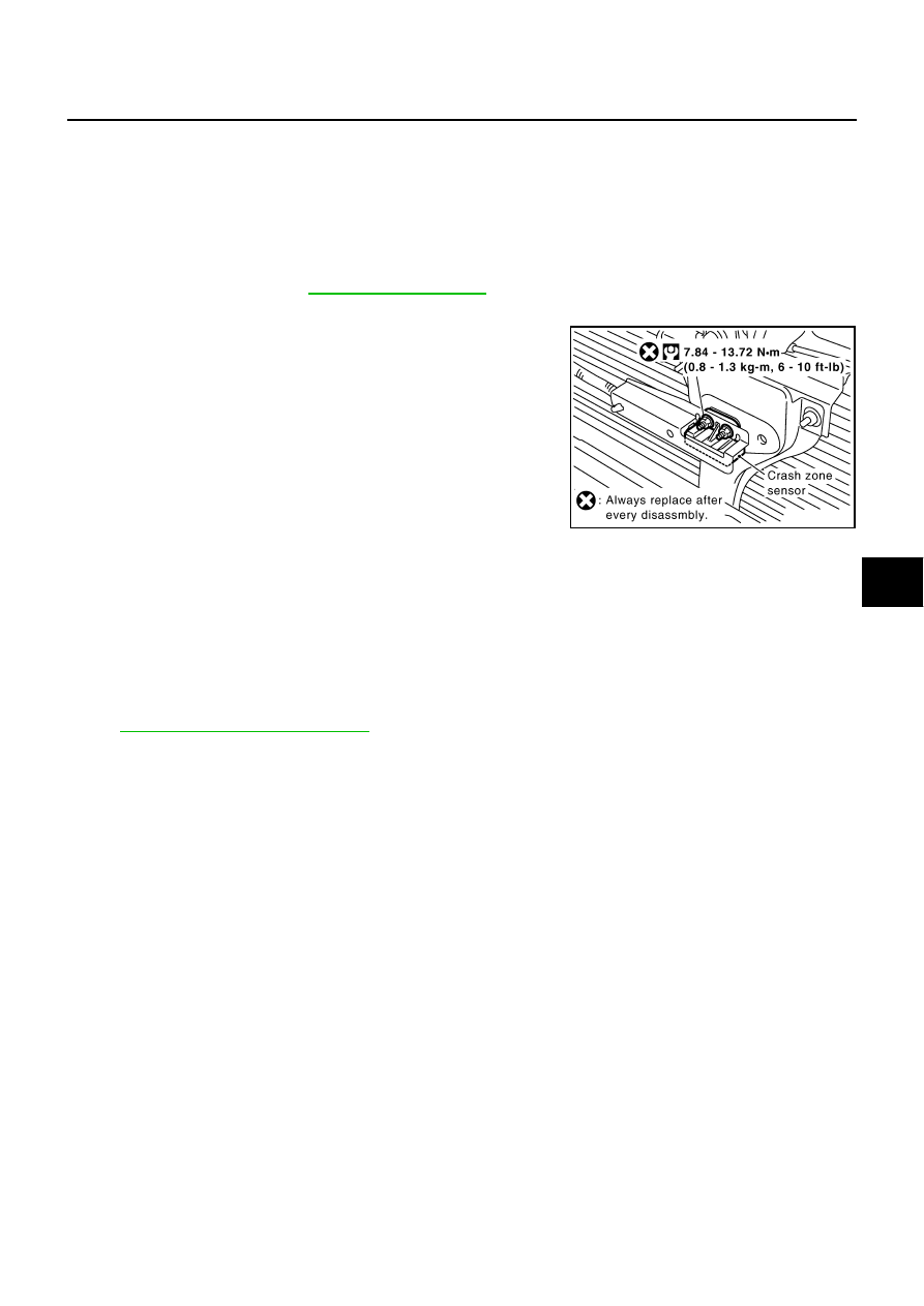
CRASH ZONE SENSOR
SRS-51
C
D
E
F
G
I
J
K
L
M
A
B
SRS
Revision: 2006 July
2007 Murano
CRASH ZONE SENSOR
PFP:98531
Removal and Installation
NHS0005U
REMOVAL
CAUTION:
●
Before servicing SRS, turn ignition switch OFF, disconnect both battery cables and wait at least 3
minutes.
●
Do not use air tools or electric tools for servicing.
1.
Remove front grille. Refer to
2.
Remove crash zone sensor connector.
3.
Remove crash zone sensor fixing nuts.
CAUTION:
●
Replace crash zone sensor if it has been dropped or sustained an impact.
●
Do not disassemble crash zone sensor.
INSTALLATION
Install in the reverse order of removal.
CAUTION:
●
Check crash zone sensor for proper installation.
●
After the work is complete, perform self-diagnosis to make sure no malfunction is detected. Refer
to
.
PHIA0259E