Nissan Murano Z50 (2007 year). Manual - part 174


  Index      Manuals     Nissan Murano Z50 (2007 year) - Service and Repair Manual


Search            copyright infringement  


Content      ..     172      173      174      175     ..


Nissan Murano Z50 (2007 year). Manual - part 174


HEATER & COOLING UNIT ASSEMBLY

ATC-119

C

D

E

F

G

H

I

K

L

M

A

B

ATC

Revision: 2006 July

2007 Murano

11. Remove rear ventilator duct1 and front floor duct. Refer to 

ATC-128, "Removal of Rear Ventilator Ducts"

and 

ATC-130, "Removal of Floor Ducts"

 .

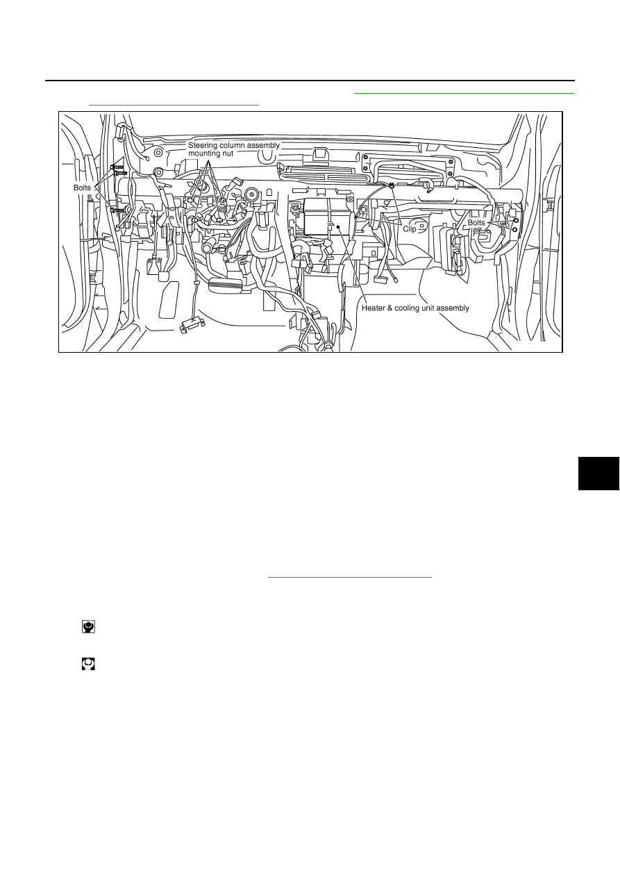
12. Remove steering member mounting bolts and steering column assembly mounting nuts, and then remove

steering member.

13. Remove heater & cooling unit assembly.

INSTALLATION

Installation is basically the reverse order of removal.

CAUTION:

Replace O-rings of low-pressure pipe 1 and high-pressure pipe 1 with new ones, and then apply
compressor oil to it when installing it.

Female-side piping connection is thin and easy to deform. Slowly insert the male-side piping
straight in axial direction.

Insert piping securely until a click is heard.

After piping connection is completed, pull male-side piping by hand to make sure that connection
does not come loose.

When recharging refrigerant, check for leaks.

NOTE:

When filling radiator with coolant, refer to 

CO-9, "Changing Engine Coolant"

 .

Recharge the refrigerant.

PJIA0095E

Heater & cooling unit assembly mounting bolt

: 6.8 N·m (0.69 kg-m, 60 in-lb) 

Steering member mounting bolt and steering column assembly mounting nut

: 12 N·m (1.2 kg-m, 9 ft-lb)

ATC-120

HEATER & COOLING UNIT ASSEMBLY

Revision: 2006 July

2007 Murano

Disassembly and Assembly

NJS000BS

1.

Adaptor duct

2.

Heater & cooling unit case (left)

3.

Mode door motor bracket

4.

Mode door motor

5.

Instrument lower cover bracket

6.

Aspirator

7.

Aspirator duct

8.

Front heater duct (left)

9.

Sub harness

10. Heater core

11.

Foot duct (passenger side)

12. Front heater duct (right)

13. Heater core cover

14. Air mix door motor (passenger side) 15. Evaporator cover

16. Low-pressure pipe 2

17. High-pressure pipe 2

18. Cooler pipe grommet

PJIA0096E

HEATER & COOLING UNIT ASSEMBLY

ATC-121

C

D

E

F

G

H

I

K

L

M

A

B

ATC

Revision: 2006 July

2007 Murano

19. Heater & cooling unit case (right)

20. Insulator

21. Air mix door motor (driver side)

22. Defroster door lever

23. Max. cool door lever

24. Main link

25. Ventilator door lever

26. Ventilator door link

27. Foot duct (left)

28. Ventilator door

29. Heater pipe support

30. Intake sensor

31. Intake sensor bracket

32. Adaptor cover

33. O-ring

34. Expansion valve

35. Evaporator

36. Defroster door

37. Defroster door link

38. Max. cool door link

39. Max. cool door (left)

40. Center case

41. Heater pipe grommet

42. Air mix door (Slide door)

43. Max. cool door (right)

: N·m (kg-m, in-lb)

: Always replace after every disassembly.

ATC-122

MODE DOOR MOTOR

Revision: 2006 July

2007 Murano

MODE DOOR MOTOR

PFP:27731

Removal and Installation

NJS000BT

REMOVAL

1.

Remove front heater duct (left). Refer to 

ATC-129, "Removal of Foot Ducts"

 .

2.

Remove BCM. Refer to 

BCS-14, "Removal and Installation of BCM"

 .

3.

Remove mode door motor mounting screws.

4.

Disconnect connector, and then remove mode door motor.

INSTALLATION

Installation is basically the reverse order of removal.

RJIA3978E

AIR MIX DOOR MOTOR

ATC-123

C

D

E

F

G

H

I

K

L

M

A

B

ATC

Revision: 2006 July

2007 Murano

AIR MIX DOOR MOTOR 

PFP:27732

Removal and Installation

NJS000BU

REMOVAL
Driver Side

1.

Set the temperature control dial (driver side) at 18

°

C (60

°

F), and then disconnect the battery cable from

the negative terminal.

2.

Remove front heater duct (left). Refer to 

ATC-129, "Removal of Foot Ducts"

 .

3.

Remove BCM. Refer to 

BCS-14, "Removal and Installation of BCM"

 .

4.

Remove mounting screws, and then remove air mix door motor.

5.

Disconnect air mix door motor connector.

Passenger Side

1.

Set the temperature control dial (passenger side) at 18

°

C (60

°

F), and then disconnect the battery cable

from the negative terminal. 

2.

Remove blower unit. Refer to 

ATC-112, "BLOWER UNIT"

 .

3.

Remove mounting screws, and then remove air mix door motor.

4.

Disconnect air mix door motor connector.

INSTALLATION

Installation is basically the reverse order of removal.

RJIA3979E

RJIA3980E

ATC-124

HEATER CORE

Revision: 2006 July

2007 Murano

HEATER CORE

PFP:27140

Removal and Installation

NJS000BV

REMOVAL

1.

Remove heater & cooling unit assembly. Refer to 

ATC-118, "HEATER & COOLING UNIT ASSEMBLY"

 .

2.

Remove air mix door motor (passenger side). Refer to 

ATC-123, "AIR MIX DOOR MOTOR"

 .

3.

Remove foot duct (right). Refer to 

ATC-129, "Removal of Foot Ducts"

 .

4.

Remove mounting screw, and then remove heater core cover.

5.

Remove mounting screw, and then remove heater pipe support and heater pipe grommet.

6.

Slide heater core (shown in the figure) to passenger side.

INSTALLATION

Installation is basically the reverse order of removal.

SJIA1189E

DUCTS AND GRILLES

ATC-125

C

D

E

F

G

H

I

K

L

M

A

B

ATC

Revision: 2006 July

2007 Murano

DUCTS AND GRILLES

PFP:27860

Removal and Installation

NJS000BW

COMPONENT LAYOUT

REMOVAL
Removal of Center Ventilator Grilles

1.

Remove center ventilator. Refer to 

IP-10, "INSTRUMENT PANEL ASSEMBLY"

 .

2.

Remove mounting clips, and then remove center ventilator
grilles.

Removal of Side Ventilator Grilles

1.

Remove side ventilator assembly. Refer to 

IP-10, "INSTRUMENT PANEL ASSEMBLY"

 .

2.

Remove mounting screw and clips, and then remove side venti-
lator grilles.

1.

Defroster nozzle

2.

Side defroster duct (left)

3.

Ventilator duct

4.

Side defroster grille (left)

5.

Side ventilator grille (left)

6.

Center ventilator grille (left)

7.

Center ventilator grille (right)

8.

Side ventilator grille (right)

9.

Instrument panel

10. Side defroster grille (right)

11. Side defroster duct (right)

RJIA3981E

RJIA1834E

RJIA1835E

ATC-126

DUCTS AND GRILLES

Revision: 2006 July

2007 Murano

Removal of Rear Ventilator Grilles

1.

Remove center pillar lower garnish. Refer to 

EI-32, "CENTER PILLAR LOWER GARNISH"

 .

2.

Remove mounting clips, and then remove rear ventilator grilles.

Removal of Defroster Nozzle, Ducts and Ventilator Ducts

1.

Remove instrument panel. Refer to 

IP-10, "INSTRUMENT PANEL ASSEMBLY"

 .

2.

Remove mounting screws, and then remove side defroster ducts, using power tools.

3.

Remove mounting screws, and then remove defroster nozzle, using power tools.

4.

Remove mounting screws, and then remove ventilator duct, using power tools.

RJIA1836E

RJIA3982E

RJIA3983E

DUCTS AND GRILLES

ATC-127

C

D

E

F

G

H

I

K

L

M

A

B

ATC

Revision: 2006 July

2007 Murano

Removal of Side Defroster Grilles

1.

Remove instrument side finisher. Refer to 

IP-10, "INSTRUMENT PANEL ASSEMBLY"

 .

2.

Remove mounting clip, and then remove side defroster grilles.

RJIA1838E

ATC-128

DUCTS AND GRILLES

Revision: 2006 July

2007 Murano

Removal of Rear Ventilator Ducts

1.

Remove center console assembly. Refer to 

IP-17, "CENTER CONSOLE ASSEMBLY"

 .

2.

Slide rear ventilator duct 2 toward vehicle rear, and then remove it.

3.

Remove mounting clips, and then remove rear ventilator duct 1.

4.

Remove floor carpet. Refer to 

EI-34, "FLOOR TRIM"

 .

5.

Remove mounting screws, and then remove rear ventilator duct 3.

RJIA1839E

RJIA1840E

DUCTS AND GRILLES

ATC-129

C

D

E

F

G

H

I

K

L

M

A

B

ATC

Revision: 2006 July

2007 Murano

Removal of Front Heater Ducts

1.

Remove mounting screw, and then remove front heater duct
(left).

2.

Remove mounting clips, and then remove front heater duct
(right).

Removal of Foot Ducts

1.

Remove instrument driver lower panel. Refer to 

IP-10, "INSTRUMENT PANEL ASSEMBLY"

 .

2.

Remove mounting screws, and then remove foot duct (driver
side).

3.

Remove blower unit. Refer to 

ATC-112, "BLOWER UNIT"

 .

4.

Remove mounting screws, and then remove foot duct (passen-
ger side).

RJIA3984E

RJIA3985E

RJIA3986E

RJIA3987E

ATC-130

DUCTS AND GRILLES

Revision: 2006 July

2007 Murano

Removal of Floor Ducts

1.

Remove front seats and center console assembly. Refer to 

SE-101, "FRONT SEAT"

  and 

IP-17, "CEN-

TER CONSOLE ASSEMBLY"

 .

2.

Slide front floor duct downward, and then remove it.

3.

Peel back floor carpet to a point where rear floor duct is visible.

4.

Remove mounting clip and harness clip, and then remove rear
floor ducts.

INSTALLATION

Installation is basically the reverse order of removal.

RJIA1843E

RJIA1844E

REFRIGERANT LINES

ATC-131

C

D

E

F

G

H

I

K

L

M

A

B

ATC

Revision: 2006 July

2007 Murano

REFRIGERANT LINES

PFP:92600

HFC-134a (R-134a) Service Procedure

NJS000BX

SETTING OF SERVICE TOOLS AND EQUIPMENT
Discharging Refrigerant

WARNING:

Avoid breathing A/C refrigerant and lubricant vapor or mist. Exposure may irritate eyes, nose and
throat. Remove HFC-134a (R-134a) from A/C system using certified service equipment meeting
requirements of SAE J-2210 [HFC-134a (R-134a) recycling equipment] or J-2209 [HFC-134a (R-134a)
recovery equipment]. If accidental system discharge occurs, ventilate work area before resuming ser-
vice. Additional health and safety information may be obtained from refrigerant and lubricant manu-
facturers.

Evacuating System and Charging Refrigerant

WJIA0614E

WJIA0615E

REFRIGERANT LINES

ATC-133

C

D

E

F

G

H

I

K

L

M

A

B

ATC

Revision: 2006 July

2007 Murano

Components

NJS000BY

Refer to 

ATC-8, "Precautions for Refrigerant Connection"

 .

PJIA0097E

ATC-134

REFRIGERANT LINES

Revision: 2006 July

2007 Murano

Removal and Installation of Compressor

NJS000D4

REMOVAL

1.

Use a refrigerant collecting equipment (for HFC-134a) to discharge the refrigerant.

2.

Remove air duct (inlet). Refer to 

EM-16, "AIR CLEANER AND AIR DUCT"

 .

3.

Remove engine undercover, using power tools.

4.

Remove mounting bolts from low-pressure flexible hose and
high-pressure flexible hose.

CAUTION:

Cap or wrap the joint of compressor, low-pressure flexible
hose and high-pressure flexible hose with suitable material
such as vinyl tape to avoid the entry of air. 

5.

Disconnect compressor connector.

6.

Remove A/C compressor belt. Refer to 

EM-13, "DRIVE BELTS"

 .

7.

Remove idler pulley bracket.

8.

Remove engine oil cooler hose bracket mounting bolts from compressor, using power tools.

9.

Remove mounting bolts and nut from compressor, using power tools.

10. Remove compressor from passenger side of the vehicle.

INSTALLATION

Installation is basically the reverse order of removal.

PJIA0123E

RJIA2983E

SJIA1166E


Content      ..     172      173      174      175     ..