Nissan Murano Z50 (2007 year). Manual - part 166
CHARGING SYSTEM
SC-21
C
D
E
F
G
H
I
J
L
M
A
B
SC
Revision: 2006 July
2007 Murano
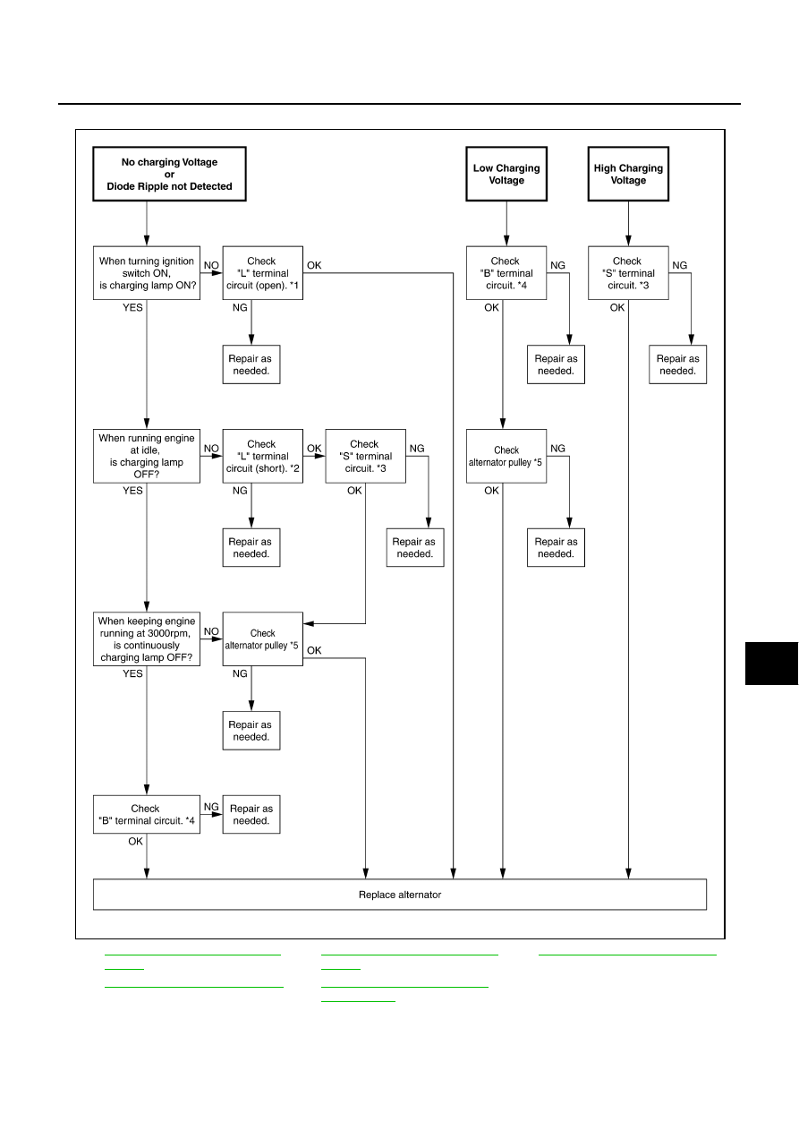
WORK FLOW
*1
SC-23, "Check “L” Terminal Circuit
(Open)"
*2
SC-23, "Check “L” Terminal Circuit
(Short)"
*3
SC-24, "Check “S” Terminal Circuit"
*4
SC-25, "Check “B” Terminal Circuit"
*5
SC-27, "ALTERNATOR PULLEY
INSPECTION"
SKIB0527E