Nissan Murano Z50 (2007 year). Manual - part 161


  Index      Manuals     Nissan Murano Z50 (2007 year) - Service and Repair Manual


Search            copyright infringement  


Content      ..     159      160      161      162     ..


Nissan Murano Z50 (2007 year). Manual - part 161


PREPARATION

RFD-5

C

E

F

G

H

I

J

K

L

M

A

B

RFD

Revision: 2006 July

2007 Murano

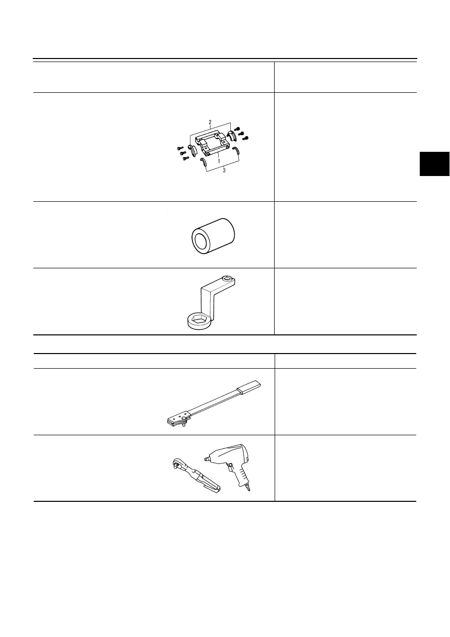
Commercial Service Tools

NDS0008D

KV381086S1
(

)

Dummy cover set

1. KV38108610

(

)

Dummy cover

2. KV38108621

(

)

Dummy cover spacer

3. KV38108630

(

)

Dummy cover shim

Checking backlash

Checking drive gear runout

Checking tooth contact

KV38108500
(

)

Drive pinion socket

Measuring preload torque

Removing and installing drive pinion nut

KV38108400
(

)

Pinion nut wrench

Measuring preload torque

Removing drive pinion nut

Tool number
(Kent-Moore No.)
Tool name

Description

SDIA2313E

ZZA1205D

ZZA1206D

Tool name

Description

Flange wrench

Removing and installing companion flange 
lock nut

Power tool

Loosening nuts and bolts

NT771

PBIC0190E

RFD-6

NOISE, VIBRATION AND HARSHNESS (NVH) TROUBLESHOOTING

Revision: 2006 July

2007 Murano

NOISE, VIBRATION AND HARSHNESS (NVH) TROUBLESHOOTING

PFP:00003

NVH Troubleshooting Chart

NDS0008E

Use the chart below to help you find the cause of the symptom. If necessary, repair or replace these parts.

×

: Applicable

Reference page

R

e

fe

r to


RFD-2

4

, "

INSPECTION A

FTER DISASSEM

BL

Y

"

 .

R

e

fe

r to


RFD-1

8

, "

T

oot

h C

ont

act

"

 .

R

e

fe

r to


RFD-2

4

, "

INSPECTION A

FTER DISASSEM

BL

Y

"

 .

R

e

fe

r to


RFD-2

0

, "

B

a

ckl

as

h

"

 .

R

e

fe

r to


RFD-2

0

, "

C

o

m

pani

on Fl

ange

 R

u

n

out

"

 .

R

e

fe

r to


RFD-8

, "

Ch

e

c

k

in

g

 Dif

fe

re

n

tia

l Ge

a

Oil

"

 .

NV

H

 in

 PR 

s

e

c

ti

o

n

.

NV

H

 in

 F

AX, 

RAX, FSU 

a

n

d

 RSU 

s

e

c

ti

o

n

s

.

NV

H

 in

 W

T

 s

e

c

tio

n

.

NV

H

 in

 W

T

 s

e

c

tio

n

.

N

V

H

 i

n

 F

AX and R

AX sec

ti

on.

NV

H

 in

 BR 

s

e

c

ti

o

n

.

NV

H

 in

 PS 

s

e

c

ti

o

n

.

Possible cause and SUSPECTED PARTS

G

e

ar

 t

oot

h r

o

u

g

h

G

e

ar

 con

ta

c

im

pr

o

per

T

oot

h sur

fa

c

es w

o

rn

B

a

ckl

as

h i

n

c

o

rr

ect

C

o

m

pani

on f

lan

ge exc

e

ssi

ve

 r

unou

t

G

e

ar

 oi

im

pr

o

per

P

R

OPE

LLER SHAFT

A

X

LE AND 

SUSPENSION

TI

R

E

S

ROAD W

H

EEL

DRIVE SHAFT

BR

AK

E

S

S

T

EERI

N

G

Symptom

Noise

×

×

×

×

×

×

×

×

×

×

×

×

×

DESCRIPTION

RFD-7

C

E

F

G

H

I

J

K

L

M

A

B

RFD

Revision: 2006 July

2007 Murano

DESCRIPTION

PFP:00000

Cross-Sectional View

NDS0008F

SDIA0141E

RFD-8

DIFFERENTIAL GEAR OIL

Revision: 2006 July

2007 Murano

DIFFERENTIAL GEAR OIL

PFP:KLD30

Changing Differential Gear Oil

NDS0008G

DRAINING

1.

Stop engine.

2.

Remove drain plug and drain oil.

3.

Set a gasket on drain plug and install it to final drive assembly
and tighten to the specified torque. Refer to 

RFD-16, "COMPO-

NENTS"

 . 

CAUTION:

Do not reuse gasket.

FILLING

1.

Remove filler plug. Fill with new oil until oil level reaches the
specified level near filler plug mounting hole.

2.

After refilling oil, check oil level. Set a gasket to filler plug, then
install it to final drive assembly. Refer to 

RFD-16, "COMPO-

NENTS"

 .

CAUTION:

Do not reuse gasket.

Checking Differential Gear Oil

NDS0008H

OIL LEAKAGE AND OIL LEVEL

Make sure that oil is not leaking from final drive assembly or around it.

Check oil level from filler plug mounting hole as shown in the fig-
ure.

CAUTION:

Do not start engine while checking oil level.

Set a gasket on filler plug and install it on final drive assembly.
Refer to 

RFD-16, "COMPONENTS"

 . 

CAUTION:

Do not reuse gasket.

PDIA0454E

Oil grade and Viscosity:

Refer to 

MA-10, "Fluids and Lubricants"

 .

Oil capacity:

Approx. 0.55  (1-1/8 US pt, 1 Imp pt)

PDIA0453E

PDIA0453E

FRONT OIL SEAL

RFD-9

C

E

F

G

H

I

J

K

L

M

A

B

RFD

Revision: 2006 July

2007 Murano

FRONT OIL SEAL

PFP:38189

Removal and Installation

NDS0008I

REMOVAL

1.

Remove propeller shaft. Refer to 

PR-5, "Removal and Installation"

 .

2.

Put matching mark on the thread edge of electric controlled cou-
pling. The matching mark should be in line with the matching
mark on companion flange.

CAUTION:

For matching mark, use paint. Do not damage electric con-
trolled coupling.

3.

Remove companion flange lock nut, using a flange wrench.
Then remove companion flange.

4.

Remove front oil seal from coupling cover, using a flat-bladed
screwdriver.

CAUTION:

Be careful not to damage coupling cover.

INSTALLATION

1.

Apply multi-purpose grease to front oil seal lips.

2.

Install front oil seal until it becomes flush with the case end,
using the drifts.

CAUTION:

Do not reuse oil seal.

When installing, do not incline oil seal.

PDIA0455E

PDIA0456E

PDIA0457E

Tool number

A: KV38100200 (J-26233)

B: ST27861000 (

)

PDIA0038E

RFD-10

FRONT OIL SEAL

Revision: 2006 July

2007 Murano

3.

Align the matching mark of electric controlled coupling with the
matching mark of companion flange, then install the companion
flange.

4.

Install companion flange lock nut with a flange wrench, tighten
the to the specified torque. Refer to 

RFD-16, "COMPONENTS"

 .

CAUTION:

Do not reuse companion flange lock nut.

5.

Install propeller shaft. Refer to 

PR-5, "Removal and Installation"

.

PDIA0455E

SIDE OIL SEAL

RFD-11

C

E

F

G

H

I

J

K

L

M

A

B

RFD

Revision: 2006 July

2007 Murano

SIDE OIL SEAL

PFP:38343

Removal and Installation

NDS0008J

REMOVAL

1.

Remove rear drive shaft. Refer to 

RAX-7, "REAR DRIVE SHAFT"

 .

2.

Remove side oil seal, using a flat-bladed screwdriver.

CAUTION:

Be careful not to damage gear carrier and rear cover.

INSTALLATION

1.

Apply multi-purpose grease to side oil seal lips.

2.

Install side oil seal until it becomes flush with the case end,
using the drift.

CAUTION:

Do not reuse oil seal.

When installing, do not incline oil seal.

3.

Install rear drive shaft. Refer to  

RAX-7, "REAR DRIVE SHAFT"

.

PDIA0431E

Tool number

: KV38100200 (J-26233)

PDIA0432E

RFD-12

ELECTRIC CONTROLLED COUPLING

Revision: 2006 July

2007 Murano

ELECTRIC CONTROLLED COUPLING

PFP:38760

Removal and Installation

NDS0008K

REMOVAL

1.

Remove propeller shaft. Refer to 

PR-5, "Removal and Installation"

 .

2.

Put matching mark on the thread edge of electric controlled cou-
pling. The matching mark should be in line with the matching
mark on the companion flange.

CAUTION:

For matching mark, use paint. Do not damage electric con-
trolled coupling.

NOTE:
When replacing electric controlled coupling, matching mark is
not necessary.

3.

Remove companion flange lock nut, using a flange wrench.

4.

Remove companion flange.

5.

Disconnect AWD solenoid harness connector and remove con-
nector bracket.

6.

Remove electric controlled coupling breather hose from cou-
pling cover.

7.

Remove coupling cover with electric controlled coupling from
gear carrier.

8.

Remove electric controlled coupling from coupling cover.

PDIA0455E

PDIA0456E

PDIA0458E

ELECTRIC CONTROLLED COUPLING

RFD-13

C

E

F

G

H

I

J

K

L

M

A

B

RFD

Revision: 2006 July

2007 Murano

INSTALLATION

1.

Install electric controlled coupling to spline of drive pinion inside
gear carrier.

CAUTION:

Align the pin on electric controlled coupling with the
groove of gear carrier.

Be careful not to damage center oil seal.

2.

Set AWD solenoid harness guide to gear carrier.

3.

Apply liquid gasket to mating surface of coupling cover. Overlap
both ends of the bead for at least 3 mm (0.12 in).

Use Genuine Silicone RTV or equivalent. Refer to 

GI-46,

"RECOMMENDED CHEMICAL PRODUCTS AND SEAL-
ANTS"

 .

CAUTION:

Remove old sealant adhering to the mounting surfaces.
Also remove any moisture, oil, or foreign material adhering
to the mounting surfaces.

4.

Install coupling cover to gear carrier with arrow facing upward,
temporarily tighten reamer bolts to the positions shown in the
figure.

5.

Tighten reamer bolts and coupling cover mounting bolts to the
specified torque. Refer to 

RFD-16, "COMPONENTS"

 .

6.

Install electric controlled coupling breather hose to coupling
cover.

7.

Install connector bracket and connect AWD solenoid harness
connector.

8.

Install companion flange.
NOTE:
When reusing electric controlled coupling, align the matching
mark of electric controlled coupling with the matching mark of
companion flange, then install companion flange.

9.

Install companion flange lock nut with flange wrench, tighten to
the specified torque. Refer to 

RFD-16, "COMPONENTS"

 .

CAUTION:

Do not reuse companion flange lock nut.

10. Install propeller shaft. Refer to 

PR-5, "Removal and Installation"

.

PDIA0463E

PDIA0613E

SDIA0587E

PDIA0455E

RFD-14

REAR FINAL DRIVE ASSEMBLY

Revision: 2006 July

2007 Murano

REAR FINAL DRIVE ASSEMBLY

PFP:38300

Removal and Installation

NDS0008L

COMPONENTS

REMOVAL

1.

Remove propeller shaft. Refer to 

PR-5, "Removal and Installation"

 .

2.

Remove stabilizer bar. Refer to 

RSU-16, "Removal and Installation"

 .

3.

Remove drive shaft. Refer to 

RAX-7, "Removal and Installation"

 .

4.

Disconnect AWD solenoid harness connector.

5.

Remove rear final drive breather hose and electric controlled coupling breather hose.

6.

Support rear final drive assembly with a suitable jack.

7.

Remove rear final drive mounting nut at rear suspension mem-
ber.

1.

Final drive mounting bracket

2.

Washer

3.

Drive shaft 

4.

Propeller shaft

5.

Rear final drive assembly

6.

Rear suspension member

PDIA0614E

PDIA0039E

REAR FINAL DRIVE ASSEMBLY

RFD-15

C

E

F

G

H

I

J

K

L

M

A

B

RFD

Revision: 2006 July

2007 Murano

8.

Remove rear final drive mounting bolts at final drive mounting
bracket with power tool, and then remove rear final drive assem-
bly.
If necessary, remove final drive mounting bracket.

CAUTION:

Secure rear final drive assembly to a suitable jack while
removing it.

INSTALLATION

Note the following, and install in the reverse order of removal.

Refer to 

RFD-14, "COMPONENTS"

  about each tightening torque.

When installing breather hoses, refer to the figure and following.

CAUTION:

Make sure there are no pinched or restricted areas on the
breather hose caused by bending or winding when install-
ing it.

For installation of rear final drive breather hose (1), the vehicle
side end breather connector (2) shall be inserted to rear suspen-
sion member (3). Install metal connector (4) side of this hose to
rear cover by inserting it with aiming painted marking (5) to the
rear of vehicle.

CAUTION:

Do not reuse breather connector.

For installation of electric controlled coupling breather hose (1),
the vehicle side end breather connector (2) shall be inserted to
rear suspension member (3). Install its metal tube to rear final
drive assembly (4) and direct the metal tube hose side end to
the front of vehicle.

When oil leaks while removing final drive assembly, check oil
level after the installation. Refer to 

RFD-8, "Checking Differential

Gear Oil"

 .

CAUTION:

Do not reuse breather connector.

PDIA0040E

PDIA1104E

PDIA1105E

RFD-16

REAR FINAL DRIVE ASSEMBLY

Revision: 2006 July

2007 Murano

Disassembly and Assembly

NDS0008M

COMPONENTS

1.

Companion flange lock nut

2.

Companion flange

3.

Front oil seal

4.

Coupling cover

5.

Reamer bolt

6.

Coupling front bearing

7.

Electric controlled coupling

8.

AWD solenoid harness

9.

Center oil seal

10. Drive pinion nut

11.

Pinion front bearing

12. Gear carrier

13. Connector bracket

14. Collapsible spacer

15. Drive pinion adjusting shim

16. Pinion rear bearing

17. Drive pinion

18. Side oil seal

19. Side bearing adjusting shim

20. Side bearing

21. Drive gear

22. Differential case

23. Side gear thrust washer

24. Side gear

25. Pinion mate thrust washer

26. Pinion mate gear

27. Pinion mate shaft

28. Lock pin

29. Rear cover

30. Filler plug

31. Drain plug

32. Gasket

A:

Oil seal lip

B:

Screw hole

Refer to 

GI-10, "Components"

 and the followings for the symbols in the figure.

:

Apply multi-purpose grease.

:

Apply gear oil.

:

Apply Genuine Silicone RTV or equivalent. Refer to 

GI-46, "Recommended Chemical Products and Sealants"

 .


:

Apply Genuine Medium Strength Thread Locking Sealant or equivalent. Refer to 

GI-46, "Recommended Chemical 

Products and Sealants"

 .

PDIA1156E

REAR FINAL DRIVE ASSEMBLY

RFD-17

C

E

F

G

H

I

J

K

L

M

A

B

RFD

Revision: 2006 July

2007 Murano

ASSEMBLY INSPECTION AND ADJUSTMENT
Total Preload Torque

1.

Remove electric controlled coupling assembly. Refer to 

RFD-21, "Electric Controlled Coupling Assembly"

.

2.

Rotate drive pinion back and forth 2 to 3 times to check for unusual noise and rotation malfunction.

3.

Rotate drive pinion at least 20 times to check for smooth opera-
tion of the bearing.

4.

Fit drive pinion socket onto drive pinion spline. Measure the total
preload, using the preload gauge.

NOTE:
Total preload torque = Pinion bearing torque + Side bearing torque

If measured value is out of the specification, disassemble it to check and adjust each part. Adjust the pin-
ion bearing preload and side bearing preload.
Adjust the pinion bearing preload first, then adjust the side bearing preload.

Drive Gear Runout

1.

Remove rear cover. Refer to 

RFD-22, "Differential Assembly"

 .

2.

Following the procedure below, install a dummy cover set to
gear carrier.

a.

Set dummy cover shims to the right and left side bearing adjust-
ing shims.

b.

Temporarily tighten dummy cover to gear carrier.

c.

Position dummy cover spacer to dummy cover.

d.

Tighten rear cover mounting bolts to the specified torque. Refer
to 

RFD-16, "COMPONENTS"

 .

e.

Tighten dummy cover spacer mounting bolts evenly to the spec-
ified torque.

Tool number

A: ST3127S000 (J-25765-A)

B: KV38108500 (

)

Total preload torque:

1.33 – 2.16 N·m (0.14 – 0.22 kg-m, 12 – 19 in-lb)

When the preload torque is large

On pinion bearings:

Replace the collapsible spacer.

On side bearings:

Use thinner side bearing adjusting shims. Refer to 

RFD-35, 

"Side Bearing Adjusting Shim"

 .

When the preload is small

On pinion bearings:

Tighten the drive pinion nut.

On side bearings:

Use thicker side bearing adjusting shims. Refer to 

RFD-35, 

"Side Bearing Adjusting Shim"

 .

PDIA0048E

Tool number

: KV381086S1 (

)

: 5.9 N·m (0.6 kg-m, 52 in-lb)

PDIA0474E

RFD-18

REAR FINAL DRIVE ASSEMBLY

Revision: 2006 July

2007 Murano

3.

Fit a dial indicator to the drive gear back face.

4.

Rotate the drive gear to measure runout.

If the runout is outside of the repair limit, check drive gear
assembly condition; foreign material may be caught between
drive gear and differential case, or differential case or drive gear
may be deformed, etc.

CAUTION:

Replace drive gear and drive pinion gear as a set.

Tooth Contact

1.

Remove rear cover. Refer to 

RFD-22, "Differential Assembly"

 .

2.

Attach dummy cover set. For dummy cover installation, refer to 

RFD-17, "Drive Gear Runout"

 .

3.

Apply red lead to drive gear.

CAUTION:

Apply red lead to both the faces of 3 to 4 gears at 4 loca-
tions evenly spaced on drive gear.

4.

Rotate drive gear back and forth several times, check drive pin-
ion gear to drive gear tooth contact.

CAUTION:

Check tooth contact on drive side and reverse side.

Runout limit:

0.05 mm (0.0020 in) or less

PDIA0050E

Tool number 

: KV381086S1 (

)

PDIA0051E

SDIA0570E

REAR FINAL DRIVE ASSEMBLY

RFD-19

C

E

F

G

H

I

J

K

L

M

A

B

RFD

Revision: 2006 July

2007 Murano

5.

If tooth contact is improperly adjusted, follow the procedure
below to adjust the pinion height (dimension X).

If the tooth contact is near the face (face contact), or near the
heal (heel contact), thicken drive pinion gear adjusting shims to
move drive pinion closer to drive gear.
Refer to 

RFD-35, "Drive Pinion Adjusting Shim"

 .

SDIA2549E

SDIA0517E

PDIA0440E

RFD-20

REAR FINAL DRIVE ASSEMBLY

Revision: 2006 July

2007 Murano

If the tooth contact is near the flank (flank contact), or near the
toe (toe contact), thin drive pinion gear adjusting shims to move
drive pinion farther from drive gear.
Refer to 

RFD-35, "Drive Pinion Adjusting Shim"

 .

Backlash

1.

Remove rear cover. Refer to 

RFD-22, "Differential Assembly"

 .

2.

Attach dummy cover set. For dummy cover installation, refer to 

RFD-17, "Drive Gear Runout"

 .

3.

Fit a dial indicator to the drive gear face to measure the back-
lash.

If the backlash is outside of the specified value, change the
thickness of side bearing adjusting shims.

Companion Flange Runout

1.

Fit a dial indicator onto the companion flange face (inner side of
the propeller shaft mounting bolt holes).

2.

Rotate companion flange to check for runout.

3.

Fit a test indicator to the inner side of companion flange (socket
diameter).

4.

Rotate companion flange to check for runout.

5.

If the runout value is outside the runout limit, follow the proce-
dure below to adjust.

a.

Check for runout while changing the phase between companion flange and drive pinion by 90

°

 step, and

search for the position where the runout is the minimum.

b.

If the runout value is still outside of the limit after the phase has been changed, replace companion flange.

c.

If the runout value is still outside of the limit after companion flange has been replaced, possible cause will
be an assembly malfunction of drive pinion and electric controlled coupling, malfunctioning coupling bear-
ing, or malfunctioning of electric controlled coupling.

PDIA0441E

Tool number 

: KV381086S1 (

)

Backlash:

0.10 - 0.15 mm (0.0039 - 0.0059 in)

When the backlash is large:

Make drive gear back adjusting shims thicker, and 
drive gear front adjusting shims thinner. Refer to 

RFD-

35, "Side Bearing Adjusting Shim"

 .

When the backlash is small:

Make drive gear back adjusting shims thinner, and 
drive gear front adjusting shims thicker. Refer to 

RFD-

35, "Side Bearing Adjusting Shim"

 .

PDIA0049E

Runout limit:

0.13 mm (0.0051 in) or less

Runout limit:

0.19 mm (0.0075 in) or less

PDIA0439E


Content      ..     159      160      161      162     ..