Nissan Murano Z50 (2007 year). Manual - part 146
PREPARATION
LU-3
C
D
E
F
G
H
I
J
K
L
M
A
LU
Revision: 2006 July
2007 Murano
PREPARATION
PFP:00002
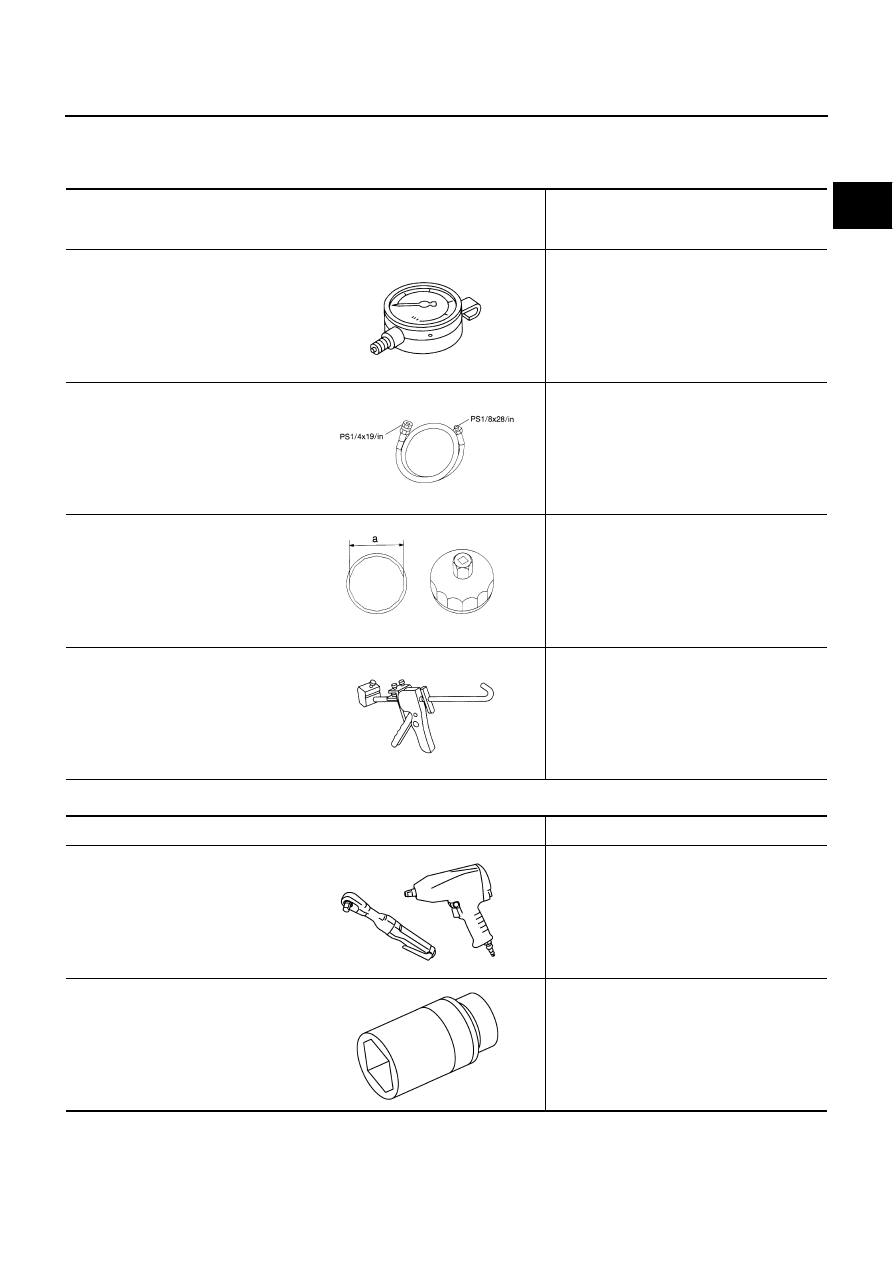
Special Service Tools
NBS002A2
The actual shapes of Kent-Moore tools may differ from those of special service tools illustrated here.
Commercial Service Tools
NBS002A3
Tool number
(Kent-Moore No.)
Tool name
Description
ST25051001
(J25695-1)
Oil pressure gauge
Measuring oil pressure
Maximum measuring range: 2,452 kPa (25
kg/cm
2
, 356 psi)
ST25052000
(J25695-2)
Hose
Adapting oil pressure gauge to oil pan (upper)
KV10115801
(J38956)
Oil filter wrench
Removing oil filter
a: 64.3 mm (2.531 in)
WS39930000
(
—
)
Tube presser
Pressing the tube of liquid gasket
NT050
S-NT559
S-NT375
NT052
Tool name
Description
Power tools
Loosening nuts and bolts
Deep socket
Removing and installing oil pressure switch
a: 27 mm (1.06 in)
PBIC0190E
PBIC4066E