Nissan Murano Z50 (2007 year). Manual - part 141
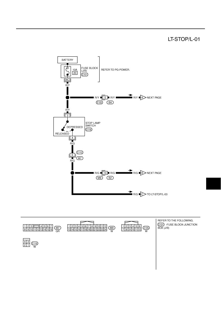
STOP LAMP
LT-159
C
D
E
F
G
H
I
J
L
M
A
B
LT
Revision: 2006 July
2007 Murano
Wiring Diagram — STOP/L —
NKS001QF
TKWB2573E
|
|
|
STOP LAMP LT-159 C D E F G H I J L M A B LT Revision: 2006 July 2007 Murano Wiring Diagram — STOP/L — NKS001QF TKWB2573E |