Nissan Murano Z50 (2007 year). Manual - part 130
TROUBLE DIAGNOSIS
LAN-77
[CAN]
C
D
E
F
G
H
I
J
L
M
A
B
LAN
Revision: 2006 July
2007 Murano
Main Line Between BCM and Data Link Connector
NKS004LH
INSPECTION PROCEDURE
1.
CHECK HARNESS CONTINUITY (OPEN CIRCUIT)
1.
Turn the ignition switch OFF.
2.
Disconnect the battery cable from the negative terminal.
3.
Disconnect ECM connector and BCM connector.
4.
Check the continuity between the BCM harness connector and the data link connector.
OK or NG
OK
>>
●
Present error: Check the following items again.
–
Decision of CAN system type.
–
Not received CONSULT-II data (SELECT SYSTEM, SELF-DIAG RESULTS, CAN DIAG SUP-
PORT MNTR).
–
Not copied from on-board diagnosis.
–
Procedure for detecting root cause.
●
Past error: Error was detected in the main line between the BCM and the data link connector.
NG
>> Repair the main line between the BCM and the data link connector.
Main Line Between Data Link Connector and ABS Actuator and Electric Unit
(Control Unit)
NKS004M2
INSPECTION PROCEDURE
1.
CHECK CONNECTOR
1.
Turn the ignition switch OFF.
2.
Disconnect the battery cable from the negative terminal.
3.
Check the following terminals and connectors for damage, bend and loose connection (connector side
and harness side).
–
Harness connector M9
–
Harness connector B2
–
Harness connector B4
–
Harness connector E105
OK or NG
OK
>> GO TO 2.
NG
>> Repair the terminal and connector.
2.
CHECK HARNESS CONTINUITY (OPEN CIRCUIT)
1.
Disconnect the harness connectors M9 and B2.
2.
Check the continuity between the data link connector and the harness connector.
OK or NG
OK
>> GO TO 3.
NG
>> Repair the main line between the data link connector and the harness connector M9.
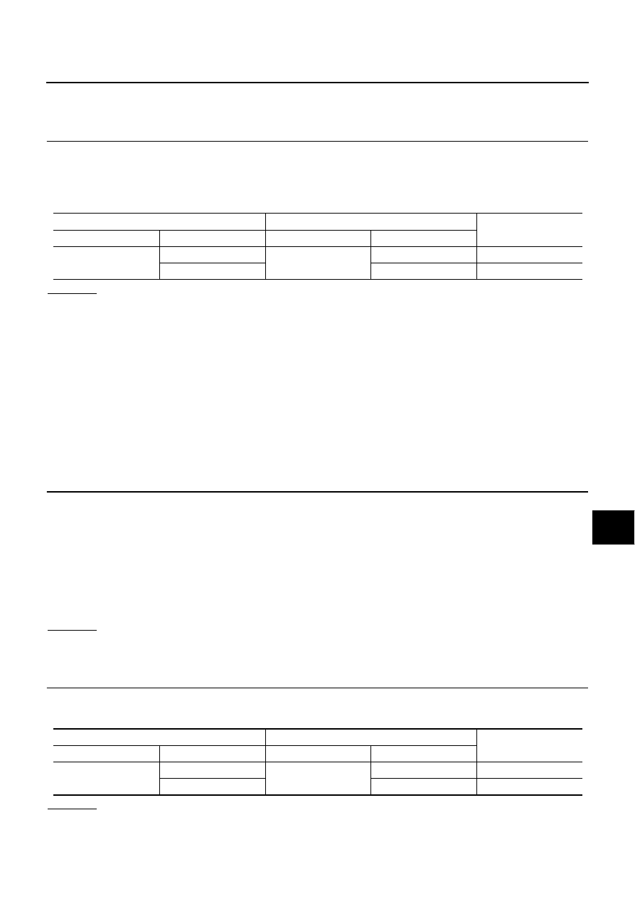
BCM harness connector
Data link connector
Continuity
Connector No.
Terminal No.
Connector No.
Terminal No.
M34
39
M24
6
Yes
40
14
Yes
Data link connector
Harness connector
Continuity
Connector No.
Terminal No.
Connector No.
Terminal No.
M24
6
M9
1
Yes
14
13
Yes