Nissan Murano Z50 (2007 year). Manual - part 127
TROUBLE DIAGNOSES WORK FLOW
LAN-29
[CAN FUNDAMENTAL]
C
D
E
F
G
H
I
J
L
M
A
B
LAN
Revision: 2006 July
2007 Murano
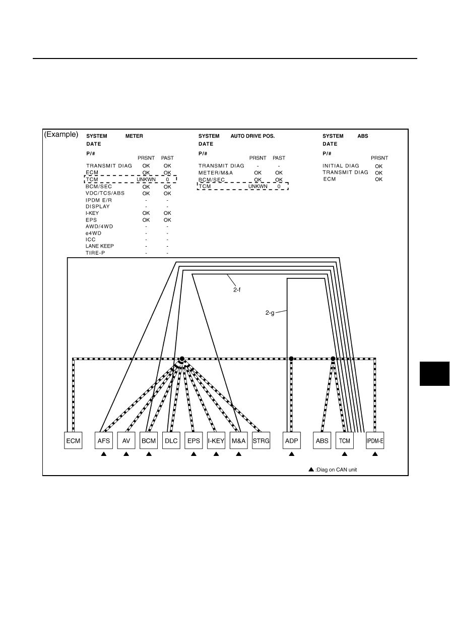
f.
Reception item of “METER”: On “TCM”, “UNKWN” is indicated. This means M&A cannot receive the sig-
nal from TCM. Draw a line to indicate an error between M&A and TCM (line 2-f in the figure).
g.
Reception item of “AUTO DRIVE POS.”: On “TCM”, “UNKWN” is indicated. This means ADP cannot
receive the signal from TCM. Draw a line to indicate an error between ADP and TCM (line 2-g in the fig-
ure).
h.
Reception item of “ABS”: “UNKWN” is not indicated. This indicates normal communication between ABS
and its receiving units. Do not draw any line.
SKIB8727E