Nissan Murano Z50 (2007 year). Manual - part 125
CENTER CONSOLE ASSEMBLY
IP-17
C
D
E
F
G
H
J
K
L
M
A
B
IP
Revision: 2006 July
2007 Murano
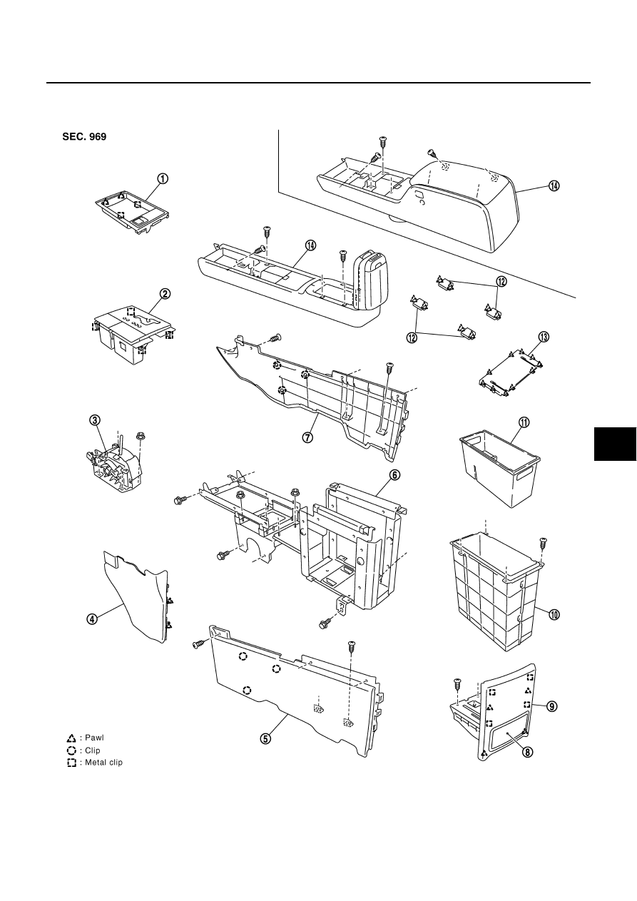
CENTER CONSOLE ASSEMBLY
PFP:96910
Component Parts Drawing
NIS001EQ
1.
Console front pocket
2.
A/T console finisher
3.
A/T control device
4.
Instrument lower cover (LH)
5.
Console cover (LH)
6.
Console reinforcement bracket
7.
Console cover RLH)
8.
Rear cup holder
9.
Console rear cover
PIIB9099E