Nissan Murano Z50 (2007 year). Manual - part 123
GW-92
REAR WINDOW DEFOGGER
Revision: 2006 July
2007 Murano
3.
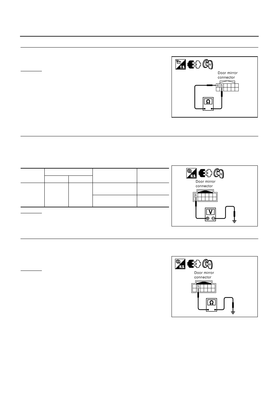
CHECK DOOR MIRROR DEFOGGER
Check continuity between door mirror terminals 6 and 5.
OK or NG
OK
>> Check the condition of the harness and the connector.
NG
>> Replace door mirror (driver side).
Check Passenger Side Door Mirror Defogger Circuit
NIS001CE
1.
CHECK POWER SUPPLY CIRCUIT
1.
Turn ignition switch OFF.
2.
Disconnect door mirror (passenger side) connector.
3.
Turn ignition switch ON.
4.
Check voltage between door mirror (passenger side) connector and ground.
OK or NG
OK
>> GO TO 2.
NG
>> Repair or replace harness.
2.
CHECK GROUND CIRCUIT
1.
Turn ignition switch OFF.
2.
Check continuity between door mirror (passenger side) connector D32 terminal 5 and ground.
OK or NG
OK
>> GO TO 3.
NG
>> Repair or replace harness.
6 – 5
: Continuity should exist.
PIIB4191E
Connector
Terminal (Wire color)
Condition
Voltage (V)
(Approx.)
(+)
(–)
D32
6 (L/B)
Ground
Rear window defogger
switch ON
Battery voltage
Rear window defogger
switch OFF
0
PIIB4190E
5 (B) – Ground
: Continuity should exist.
PIIB4189E