Nissan Murano Z50 (2007 year). Manual - part 103
 

  Index      Manuals     Nissan Murano Z50 (2007 year) - Service and Repair Manual


Search            copyright infringement  


Content      ..     101      102      103      104     ..


Nissan Murano Z50 (2007 year). Manual - part 103


DTC P2A00, P2A03 A/F SENSOR 1

EC-597

C

D

E

F

G

H

I

J

K

L

M

A

EC

Revision: 2006 July

2007 Murano

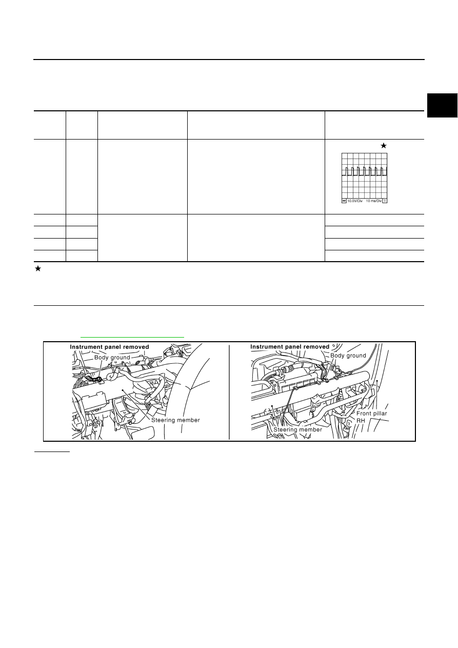
Specification data are reference values and are measured between each terminal and ground.
Pulse signal is measured by CONSULT-II.

CAUTION:

Do not use ECM ground terminals when measuring input/output voltage. Doing so may result in dam-
age to the ECM's transistor. Use a ground other than ECM terminals, such as the ground.

: Average voltage for pulse signal (Actual pulse signal can be confirmed by oscilloscope.)

Diagnostic Procedure

NBS0039V

1. 

CHECK GROUND CONNECTIONS

1.

Turn ignition switch OFF.

2.

Loosen and retighten two ground screws on the body.
Refer to 

EC-150, "Ground Inspection"

 .

OK or NG

OK

>> GO TO 2.

NG

>> Repair or replace ground connections.

TERMI-

NAL 

NO.

WIRE 

COLOR

ITEM

CONDITION

DATA (DC Voltage)

24

V

A/F sensor 1 heater
 (Bank 2)

[Engine is running]

Warm-up condition

Idle speed

Approximately 5V

57

P

A/F sensor 1 (Bank 2)

[Engine is running]

Warm-up condition

Idle speed

Approximately 2.6V

58

SB

Approximately 2.3V

76

G/Y

Approximately 3.1V

77

LG

Approximately 2.3V

PBIB1584E

PBIB1835E

EC-598

DTC P2A00, P2A03 A/F SENSOR 1

Revision: 2006 July

2007 Murano

2. 

RETIGHTEN AIR FUEL RATIO (A/F) SENSOR 1

Loosen and retighten the air fuel ratio (A/F) sensor 1.

>> GO TO 3.

3. 

CHECK FOR INTAKE AIR LEAK

1.

Start engine and run it at idle.

2.

Listen for an intake air leak after the mass air flow sensor.

OK or NG

OK

>> GO TO 4.

NG

>> Repair or replace.

Tightening torque: 40 - 60 N-m (4.1 - 6.1 kg-m, 30 - 44 ft-lb)

PBIB2291E

DTC P2A00, P2A03 A/F SENSOR 1

EC-599

C

D

E

F

G

H

I

J

K

L

M

A

EC

Revision: 2006 July

2007 Murano

4. 

CLEAR THE SELF-LEARNING DATA.

 With CONSULT-II

1.

Start engine and warm it up to normal operating temperature.

2.

Select “SELF-LEARNING CONT” in “WORK SUPPORT” mode with CONSULT-II.

3.

Clear the self-learning control coefficient by touching “CLEAR”.

4.

Run engine for at least 10 minutes at idle speed.
Is the 1st trip DTC P0171, P0172, P0174 or P0175 detected?
Is it difficult to start engine?

 Without CONSULT-II

1.

Start engine and warm it up to normal operating temperature.

2.

Turn ignition switch OFF.

3.

Disconnect mass air flow sensor harness connector.

4.

Restart engine and let it idle for at least 5 seconds.

5.

Stop engine and reconnect mass air flow sensor harness con-
nector.

6.

Make sure DTC P0102 is displayed.

7.

Erase the DTC memory. Refer to 

EC-58, "HOW TO ERASE

EMISSION-RELATED DIAGNOSTIC INFORMATION"

 .

8.

Make sure DTC P0000 is displayed.

9.

Run engine for at least 10 minutes at idle speed.
Is the 1st trip DTC P0171, P0172, P0174 or P0175 detected?
Is it difficult to start engine?

Yes or No

Yes

>> Perform trouble diagnosis for DTC P0171, P0172 or P0174, P0175. Refer to 

EC-306

 , 

EC-318

 .

No

>> GO TO 5.

SEF968Y

PBIB1353E

EC-600

DTC P2A00, P2A03 A/F SENSOR 1

Revision: 2006 July

2007 Murano

5. 

CHECK HARNESS CONNECTOR

1.

Turn ignition switch OFF.

2.

Disconnect A/F sensor 1 harness connector.

3.

Check harness connector for water. 
Water should not exit.

OK or NG

OK

>> GO TO 6.

NG

>> Repair or replace harness connector.

6. 

CHECK AIR FUEL RATIO (A/F) SENSOR 1 POWER SUPPLY CIRCUIT

1.

Turn ignition switch OFF.

2.

Disconnect air fuel ratio (A/F) sensor 1 harness connector.

3.

Turn ignition switch ON.

4.

Check voltage between A/F sensor 1 terminal 3 and ground with
CONSULT-II or tester.

OK or NG

OK

>> GO TO 12.

NG

>> GO TO 7.

PBIB2293E

Voltage: Battery voltage

PBIB2293E

PBIB1683E

DTC P2A00, P2A03 A/F SENSOR 1

EC-601

C

D

E

F

G

H

I

J

K

L

M

A

EC

Revision: 2006 July

2007 Murano

7. 

CHECK CONDENSER CIRCUIT-I

1.

Turn ignition switch OFF.

2.

Disconnect fuse block (J/B) harness connector M1.

3.

Check resistance between fuse block (J/B) terminal 9A and ground.
Refer to Wiring Diagram. 

OK or NG

OK

>> GO TO 8.

NG

>> GO TO 9.

8. 

DETECT MALFUNCTIONING PART

Check the following.

Harness connectors M82, F102

Fuse block (J/B) connector M1

15A fuse

Harness for open or short between A/F sensor 1 and fuse

>> Repair harness or connectors.

9. 

CHECK CONDENSER CIRCUIT-II

1.

Disconnect condenser harness connectors.

2.

Check harness continuity between fuse block (J/B) terminal 9A and condenser terminal 1, condenser ter-
minal 2 and ground.
Refer to Wiring Diagram. 

3.

Also check harness for short to ground and short to power.

OK or NG

OK

>> GO TO 10.

NG

>> Repair harness or connectors.

10. 

CHECK CONDENSER

Refer to 

EC-168, "CONDENSER"

 .

OK or NG

OK

>> GO TO 11.

NG

>> Replace condenser.

11. 

CHECK INTERMITTENT INCIDENT

Refer to 

EC-141, "TROUBLE DIAGNOSIS FOR INTERMITTENT INCIDENT"

 .

>> INSPECTION END

Resistance: Above 1M

 [at 25

°

C (77

°

F)]

Continuity should exist.

EC-602

DTC P2A00, P2A03 A/F SENSOR 1

Revision: 2006 July

2007 Murano

12. 

CHECK A/F SENSOR 1 INPUT SIGNAL CIRCUIT

1.

Turn ignition switch OFF.

2.

Disconnect ECM harness connector.

3.

Check harness continuity between the following terminals.
Refer to Wiring Diagram.

4.

Check harness continuity between the following terminals and ground.
Refer to Wiring Diagram.

5.

Also check harness for short to power.

OK or NG

OK

>> GO TO 13.

NG

>> Repair open circuit or short to ground or short to power in harness or connectors.

13. 

CHECK A/F SENSOR 1 HEATER

Refer to 

EC-168, "Component Inspection"

 .

OK or NG

OK

>> GO TO 14.

NG

>> GO TO 15.

14. 

CHECK INTERMITTENT INCIDENT

Perform 

EC-141, "TROUBLE DIAGNOSIS FOR INTERMITTENT INCIDENT"

 .

OK or NG

OK

>> GO TO 15.

NG

>> Repair or replace.

A/F sensor 1 terminal

ECM terminal

Bank 1

1

16

2

75

5

35

6

56

Bank 2

1

76

2

77

5

57

6

58

Continuity should exist.

Bank 1

Bank 2

A/F sensor 1 terminal

ECM terminal

A/F sensor 1 terminal

ECM terminal

1

16

1

76

2

75

2

77

5

35

5

57

6

56

6

58

Continuity should not exist.

DTC P2A00, P2A03 A/F SENSOR 1

EC-603

C

D

E

F

G

H

I

J

K

L

M

A

EC

Revision: 2006 July

2007 Murano

15. 

REPLACE AIR FUEL RATIO (A/F) SENSOR 1

Replace malfunctioning air fuel ratio (A/F) sensor 1.

CAUTION:

Discard any air fuel ratio (A/F) sensor which has been dropped from a height of more than 0.5 m
(19.7 in) onto a hard surface such as a concrete floor; use a new one.

Before installing new air fuel ratio (A/F) sensor, clean exhaust system threads using Heated Oxy-
gen Sensor Thread Cleaner tool J-43897-18 or J-43897-12 and approved anti-seize lubricant.

>> GO TO 16.

16. 

CONFIRM A/F ADJUSTMENT DATA

1.

Turn ignition switch ON.

2.

Select “A/F ADJ-B1” and “A/F ADJ-B2” in “DATA MONITOR”
mode with CONSULT-II.

3.

Make sure that “0.000” is displayed on CONSULT-II screen.

OK or NG

OK

>> INSPECTION END

NG

>> GO TO 17.

PBIB3202E

EC-604

DTC P2A00, P2A03 A/F SENSOR 1

Revision: 2006 July

2007 Murano

17. 

CLEAR A/F ADJUSTMENT DATA

 With CONSULT-II

1.

Start engine and warm it up to normal operating temperature.

2.

Select “SELF-LEARNING CONT” in “WORK SUPPORT” mode with CONSULT-II.

3.

Clear the self-learning control coefficient by touching “CLEAR”.

 Without CONSULT-II

1.

Start engine and warm it up to normal operating temperature.

2.

Turn ignition switch OFF.

3.

Disconnect mass air flow sensor harness connector.

4.

Restart engine and let it idle for at least 5 seconds.

5.

Stop engine and reconnect mass air flow sensor harness con-
nector.

6.

Make sure DTC P0102 is displayed.

7.

Erase the DTC memory. Refer to 

EC-58, "HOW TO ERASE

EMISSION-RELATED DIAGNOSTIC INFORMATION"

 .

8.

Make sure DTC P0000 is displayed.

>> GO TO 18.

18. 

CONFIRM A/F ADJUSTMENT DATA

1.

Turn ignition switch OFF and then ON.

2.

Select “A/F ADJ-B1” and “A/F ADJ-B2” in “DATA MONITOR”
mode with CONSULT-II.

3.

Make sure that “0.000” is displayed on CONSULT-II screen.

>> INSPECTION END

Removal and Installation

NBS0039W

AIR FUEL RATIO (A/F) SENSOR 1

Refer to 

EM-25, "EXHAUST MANIFOLD AND THREE WAY CATALYST"

 .

SEF968Y

PBIB1353E

PBIB3202E

ASCD BRAKE SWITCH

EC-605

C

D

E

F

G

H

I

J

K

L

M

A

EC

Revision: 2006 July

2007 Murano

ASCD BRAKE SWITCH

PFP:25320

Component Description

NBS003EE

When the brake pedal is depressed, ASCD brake switch is turned
OFF and stop lamp switch is turned ON. ECM detects the state of
the brake pedal by this input of two kinds (ON/OFF signal).
Refer to 

EC-27, "AUTOMATIC SPEED CONTROL DEVICE (ASCD)"

for the ASCD function.

CONSULT-II Reference Value in Data Monitor Mode

NBS003EF

Specification data are reference values.

PBIB1368E

MONITOR ITEM

CONDITION

SPECIFICATION

BRAKE SW1
(ASCD brake switch)

Ignition switch: ON

Brake pedal: Fully released

ON

Brake pedal: Slightly depressed

OFF

BRAKE SW2
(stop lamp switch)

Ignition switch: ON

Brake pedal: Fully released

OFF

Brake pedal: Slightly depressed

ON

EC-606

ASCD BRAKE SWITCH

Revision: 2006 July

2007 Murano

Wiring Diagram

NBS003EG

TBWB0823E

ASCD BRAKE SWITCH

EC-607

C

D

E

F

G

H

I

J

K

L

M

A

EC

Revision: 2006 July

2007 Murano

Specification data are reference values and are measured between each terminal and ground.

CAUTION:

Do not use ECM ground terminals when measuring input/output voltage. Doing so may result in dam-
age to the ECM's transistor. Use a ground other than ECM terminals, such as the ground.

Diagnostic Procedure

NBS003EH

1. 

CHECK OVERALL FUNCTION-I

 With CONSULT-II

1.

Turn ignition switch ON.

2.

Select “BRAKE SW1” in “DATA MONITOR” mode with CONSULT-II.

3.

Check “BRAKE SW1” indication under the following conditions.

 Without CONSULT-II

1.

Turn ignition switch ON.

2.

Check voltage between ECM terminal 108 and ground under the
following conditions.

OK or NG

OK

>> GO TO 2.

NG

>> GO TO 3.

TER-

MINAL 

NO.

WIRE 

COLOR

ITEM

CONDITION

DATA (DC Voltage)

101

R/G

Stop lamp switch

[Ignition switch: OFF]

Brake pedal: Fully released

Approximately 0V

[Ignition switch: OFF]

Brake pedal: Slightly depressed

BATTERY VOLTAGE
(11 - 14V)

108

L/B

ASCD brake switch

[Ignition switch: ON]

Brake pedal: Slightly depressed

Approximately 0V

[Ignition switch: ON]

Brake pedal: Fully released

BATTERY VOLTAGE
(11 - 14V)

CONDITION

INDICATION

Brake pedal: Slightly depressed

OFF

Brake pedal: Fully released

ON

SEC011D

CONDITION

VOLTAGE

Brake pedal: Slightly depressed

Approximately 0V

Brake pedal: Fully released

Battery voltage

MBIB0061E

EC-608

ASCD BRAKE SWITCH

Revision: 2006 July

2007 Murano

2. 

CHECK OVERALL FUNCTION-II

 With CONSULT-II

Check “BRAKE SW2” indication in “DATA MONITOR” mode. 

 Without CONSULT-II

Check voltage between ECM terminal 101 and ground under the following conditions.

OK or NG

OK

>> INSPECTION END

NG

>> GO TO 8.

CONDITION

INDICATION

Brake pedal: Fully released

OFF

Brake pedal: Slightly depressed

ON

SEC013D

CONDITION

VOLTAGE

Brake pedal: Fully released

Approximately 0V

Brake pedal: Slightly depressed

Battery voltage

MBIB0060E

ASCD BRAKE SWITCH

EC-609

C

D

E

F

G

H

I

J

K

L

M

A

EC

Revision: 2006 July

2007 Murano

3. 

CHECK ASCD BRAKE SWITCH POWER SUPPLY CIRCUIT

1.

Turn ignition switch OFF.

2.

Disconnect ASCD brake switch harness connector.

3.

Turn ignition switch ON.

4.

Check voltage between ASCD brake switch terminal 1 and
ground with CONSULT-II or tester.

OK or NG

OK

>> GO TO 5.

NG

>> GO TO 4.

4. 

DETECT MALFUNCTIONING PART

Check the following.

Fuse block (J/B) connector E101

10A fuse

Harness for open or short between ASCD brake switch and fuse

>> Repair open circuit or short to ground or short to power in harness or connectors.

5. 

CHECK ASCD BRAKE SWITCH INPUT SIGNAL CIRCUIT FOR OPEN AND SHORT

1.

Turn ignition switch OFF.

2.

Disconnect ECM harness connector.

3.

Check harness continuity between ECM terminal 108 and ASCD brake switch terminal 2.
Refer to Wiring Diagram.

4.

Also check harness for short to ground and short to power.

OK or NG

OK

>> GO TO 7.

NG

>> GO TO 6.

6. 

DETECT MALFUNCTIONING PART

Check the following.

Harness connectors E109, M6

Harness for open or short between ECM and ASCD brake switch

>> Repair open circuit or short to ground or short to power in harness or connectors.

PBIB1368E

Voltage: Battery voltage

PBIB0857E

Continuity should exist.

EC-610

ASCD BRAKE SWITCH

Revision: 2006 July

2007 Murano

7. 

CHECK ASCD BRAKE SWITCH

Refer to 

EC-528, "Component Inspection"

 .

OK or NG

OK

>> GO TO 13.

NG

>> Replace ASCD brake switch.

8. 

CHECK STOP LAMP SWITCH POWER SUPPLY CIRCUIT

1.

Turn ignition switch OFF.

2.

Disconnect stop lamp switch harness connector.

3.

Check voltage between stop lamp switch terminal 3 and ground
with CONSULT -II or tester.

OK or NG

OK

>> GO TO 10.

NG

>> GO TO 9.

9. 

DETECT MALFUNCTIONING PART

Check the following.

Fuse block (J/B) connector E101

10A fuse

Harness for open or short between stop lamp switch and battery

>> Repair open circuit or short to ground or short to power in harness or connectors.

10. 

CHECK STOP LAMP SWITCH INPUT SIGNAL CIRCUIT FOR OPEN AND SHORT

1.

Disconnect ECM harness connector.

2.

Check harness continuity between ECM terminal 101 and stop lamp switch terminal 4.
Refer to Wiring Diagram.

3.

Also check harness for short to ground and short to power.

OK or NG

OK

>> GO TO 12.

NG

>> GO TO 11.

PBIB1368E

Voltage: Battery voltage

PBIB2102E

Continuity should exist.

ASCD BRAKE SWITCH

EC-611

C

D

E

F

G

H

I

J

K

L

M

A

EC

Revision: 2006 July

2007 Murano

11. 

DETECT MALFUNCTIONING PART

Check the following.

Harness connectors E110, M7

Harness for open or short between ECM and stop lamp switch

>> Repair open circuit or short to ground or short to power in harness or connectors.

12. 

CHECK STOP LAMP SWITCH

Refer to 

EC-528, "Component Inspection"

 .

OK or NG

OK

>> GO TO 13.

NG

>> Replace stop lamp switch.

13. 

CHECK INTERMITTENT INCIDENT

Refer to 

EC-141, "TROUBLE DIAGNOSIS FOR INTERMITTENT INCIDENT"

 .

>> INSPECTION END

Component Inspection

NBS003EI

ASCD BRAKE SWITCH

1.

Turn ignition switch OFF.

2.

Disconnect ASCD brake switch harness connector.

3.

Check continuity between ASCD brake switch terminals 1 and 2
under the following conditions.

If NG, adjust ASCD brake switch installation, refer to 

BR-7,

"BRAKE PEDAL"

 , and perform step 3 again.

STOP LAMP SWITCH

1.

Turn ignition switch OFF.

2.

Disconnect stop lamp switch harness connector.

3.

Check continuity between stop lamp switch terminals 3 and 4
under the following conditions.

If NG, adjust stop lamp switch installation, refer to 

BR-7,

"BRAKE PEDAL"

 , and perform step 3 again.

Condition

Continuity

Brake pedal: Fully released

Should exist

Brake pedal: Slightly depressed

Should not exist

SEC023D

Condition

Continuity

Brake pedal: Fully released

Should not exist

Brake pedal: Slightly depressed

Should exist

PBIB2103E

EC-612

ASCD INDICATOR

Revision: 2006 July

2007 Murano

ASCD INDICATOR

PFP:24814

Component Description

NBS003EJ

ASCD indicator lamp illuminates to indicate ASCD operation status. Lamp has two indicators, CRUISE and
SET, and is integrated in combination meter.
CRUISE indicator illuminates when MAIN switch on ASCD steering switch is turned ON to indicated that
ASCD system is ready for operation.
SET indicator illuminates when following conditions are met. 

CRUISE indicator is illuminated.

SET/COAST switch on ASCD steering switch is turned ON while vehicle speed is within the range of
ASCD setting.

SET indicator remains lit during ASCD control.
Refer to 

EC-27, "AUTOMATIC SPEED CONTROL DEVICE (ASCD)"

   for the ASCD function.

CONSULT-II Reference Value in Data Monitor Mode

NBS003EK

Specification data are reference value.

MONITOR ITEM

CONDITION

SPECIFICATION

CRUISE LAMP

Ignition switch: ON

MAIN switch: Pressed at the 1st time 

 at the 2nd time

ON 

 OFF

SET LAMP

MAIN switch: ON

When vehicle speed is between 
40 km/h (25 MPH) and 144 km/h 
(89 MPH)

ASCD: Operating

ON

ASCD: Not operating

OFF


Content      ..     101      102      103      104     ..