Nissan Murano Z50 (2007 year). Manual - part 101
DTC P2122, P2123 APP SENSOR
EC-565
C
D
E
F
G
H
I
J
K
L
M
A
EC
Revision: 2006 July
2007 Murano
DTC P2122, P2123 APP SENSOR
PFP:18002
Component Description
NBS003CK
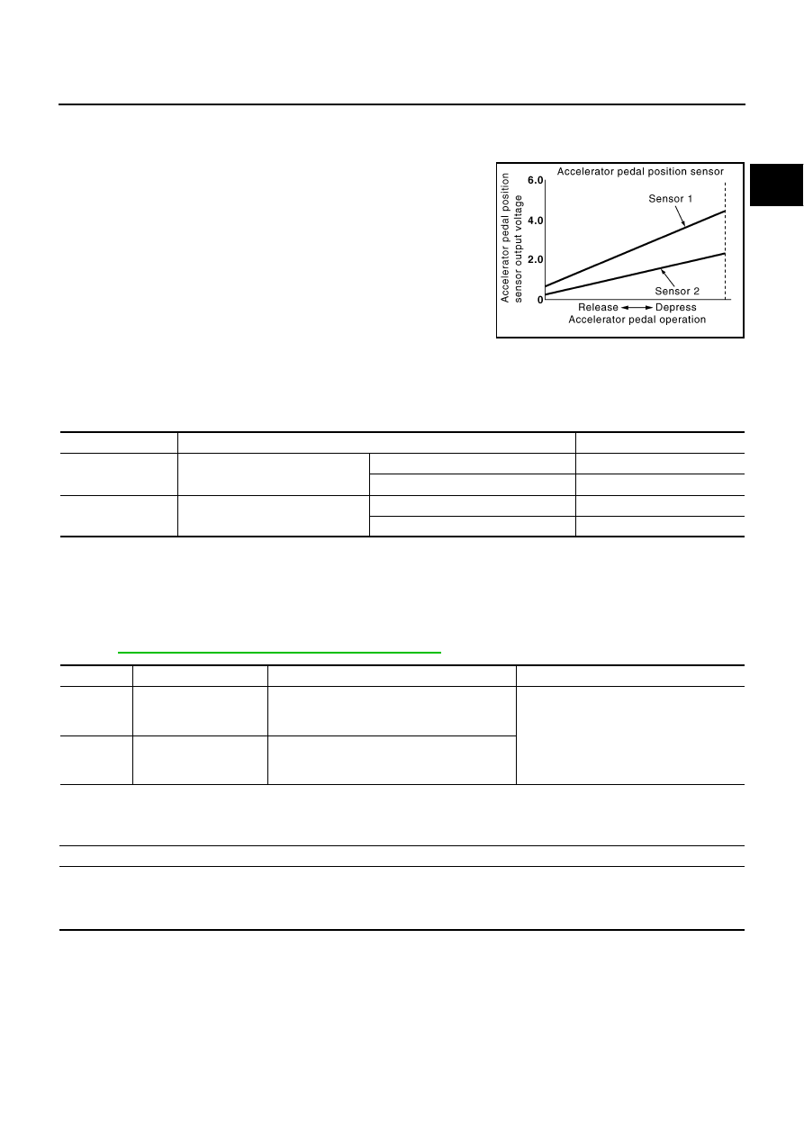
The accelerator pedal position sensor is installed on the upper end
of the accelerator pedal assembly. The sensor detects the accelera-
tor position and sends a signal to the ECM.
Accelerator pedal position sensor has two sensors. These sensors
are a kind of potentiometers which transform the accelerator pedal
position into output voltage, and emit the voltage signal to the ECM.
In addition, these sensors detect the opening and closing speed of
the accelerator pedal and feed the voltage signals to the ECM. The
ECM judges the current opening angle of the accelerator pedal from
these signals and controls the throttle control motor based on these
signals.
Idle position of the accelerator pedal is determined by the ECM
receiving the signal from the accelerator pedal position sensor. The ECM uses this signal for the engine oper-
ation such as fuel cut.
CONSULT-II Reference Value in Data Monitor Mode
NBS003CL
Specification data are reference values.
*: Accelerator pedal position sensor 2 signal is converted by ECM internally. Thus, it differ from ECM terminal voltage.
On Board Diagnosis Logic
NBS003CM
These self-diagnoses have the one trip detection logic.
NOTE:
If DTC P2122 or P2123 is displayed with DTC P0643, first perform the trouble diagnosis for DTC P0643.
Refer to
EC-485, "DTC P0643 SENSOR POWER SUPPLY"
FAIL-SAFE MODE
When the malfunction is detected, ECM enters fail-safe mode and the MIL lights up.
PBIB1741E
MONITOR ITEM
CONDITION
SPECIFICATION
ACCEL SEN 1
ACCEL SEN 2*
●
Ignition switch: ON
(Engine stopped)
Accelerator pedal: Fully released
0.5 - 1.0V
Accelerator pedal: Fully depressed
4.2 - 4.8V
CLSD THL POS
●
Ignition switch: ON
(Engine stopped)
Accelerator pedal: Fully released
ON
Accelerator pedal: Slightly depressed
OFF
DTC No.
Trouble diagnosis name
DTC detecting condition
Possible cause
P2122
2122
Accelerator pedal posi-
tion sensor 1 circuit low
input
An excessively low voltage from the APP sen-
sor 1 is sent to ECM.
●
Harness or connectors
(APP sensor 1 circuit is open or
shorted.)
●
Accelerator pedal position sensor
(APP sensor 1)
P2123
2123
Accelerator pedal posi-
tion sensor 1 circuit high
input
An excessively high voltage from the APP sen-
sor 1 is sent to ECM.
Engine operating condition in fail-safe mode
The ECM controls the electric throttle control actuator in regulating the throttle opening in order for the idle position to be within +10
degrees.
The ECM regulates the opening speed of the throttle valve to be slower than the normal condition.
So, the acceleration will be poor.