Nissan Murano Z50 (2007 year). Manual - part 98
DTC P1564 ASCD STEERING SWITCH
EC-517
C
D
E
F
G
H
I
J
K
L
M
A
EC
Revision: 2006 July
2007 Murano
Specification data are reference values and are measured between each terminal and ground.
CAUTION:
Do not use ECM ground terminals when measuring input/output voltage. Doing so may result in dam-
age to the ECM's transistor. Use a ground other than ECM terminals, such as the ground.
Diagnostic Procedure
NBS003BA
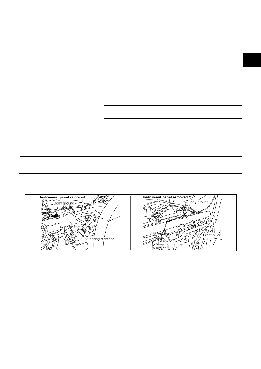
1.
CHECK GROUND CONNECTIONS
1.
Turn ignition switch OFF.
2.
Loosen and retighten two ground screws on the body.
Refer to
OK or NG
OK
>> GO TO 2.
NG
>> Repair or replace ground connections.
TER-
MINAL
NO.
WIRE
COLOR
ITEM
CONDITION
DATA (DC Voltage)
67
B
Sensor ground
[Engine is running]
●
Warm-up condition
●
Idle speed
Approximately 0V
99
G/Y
ASCD steering switch
[Ignition switch: ON]
●
ASCD steering switch: OFF
Approximately 4V
[Ignition switch: ON]
●
MAIN switch: Pressed
Approximately 0V
[Ignition switch: ON]
●
CANCEL switch: Pressed
Approximately 1V
[Ignition switch: ON]
●
RESUME/ACCELERATE switch: Pressed
Approximately 3V
[Ignition switch: ON]
●
SET/COAST switch: Pressed
Approximately 2V
PBIB1835E