Nissan Murano Z50 (2007 year). Manual - part 89
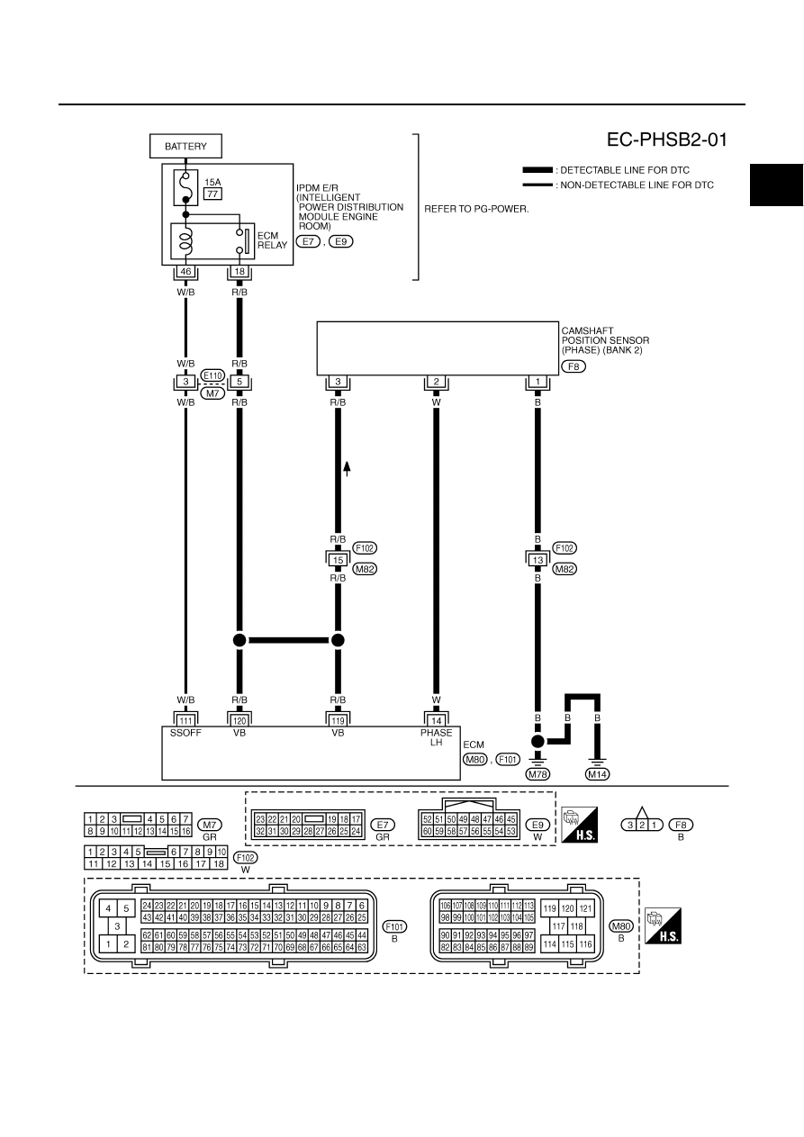
DTC P0340, P0345 CMP SENSOR (PHASE)
EC-373
C
D
E
F
G
H
I
J
K
L
M
A
EC
Revision: 2006 July
2007 Murano
BANK 2
TBWB0803E
|
|
|
DTC P0340, P0345 CMP SENSOR (PHASE) EC-373 C D E F G H I J K L M A EC Revision: 2006 July 2007 Murano BANK 2 TBWB0803E |