Nissan Murano Z50 (2007 year). Manual - part 85
DTC P0171, P0174 FUEL INJECTION SYSTEM FUNCTION
EC-309
C
D
E
F
G
H
I
J
K
L
M
A
EC
Revision: 2006 July
2007 Murano
Specification data are reference values and are measured between each terminal and ground.
Pulse signal is measured by CONSULT-II.
CAUTION:
Do not use ECM ground terminals when measuring input/output voltage. Doing so may result in dam-
age to the ECM's transistor. Use a ground other than ECM terminals, such as the ground.
: Average voltage for pulse signal (Actual pulse signal can be confirmed by oscilloscope.)
TERMI-
NAL
NO.
WIRE
COLOR
ITEM
CONDITION
DATA (DC Voltage)
2
G/B
A/F sensor 1 heater
(Bank 1)
[Engine is running]
●
Warm-up condition
●
Idle speed
Approximately 5V
16
LG/B
A/F sensor 1 (Bank 1)
[Engine is running]
●
Warm-up condition
●
Idle speed
Approximately 3.1V
35
O/L
Approximately 2.6V
56
BR/Y
Approximately 2.3V
75
Y/R
Approximately 2.3V
21
22
23
L/W
R/Y
R/B
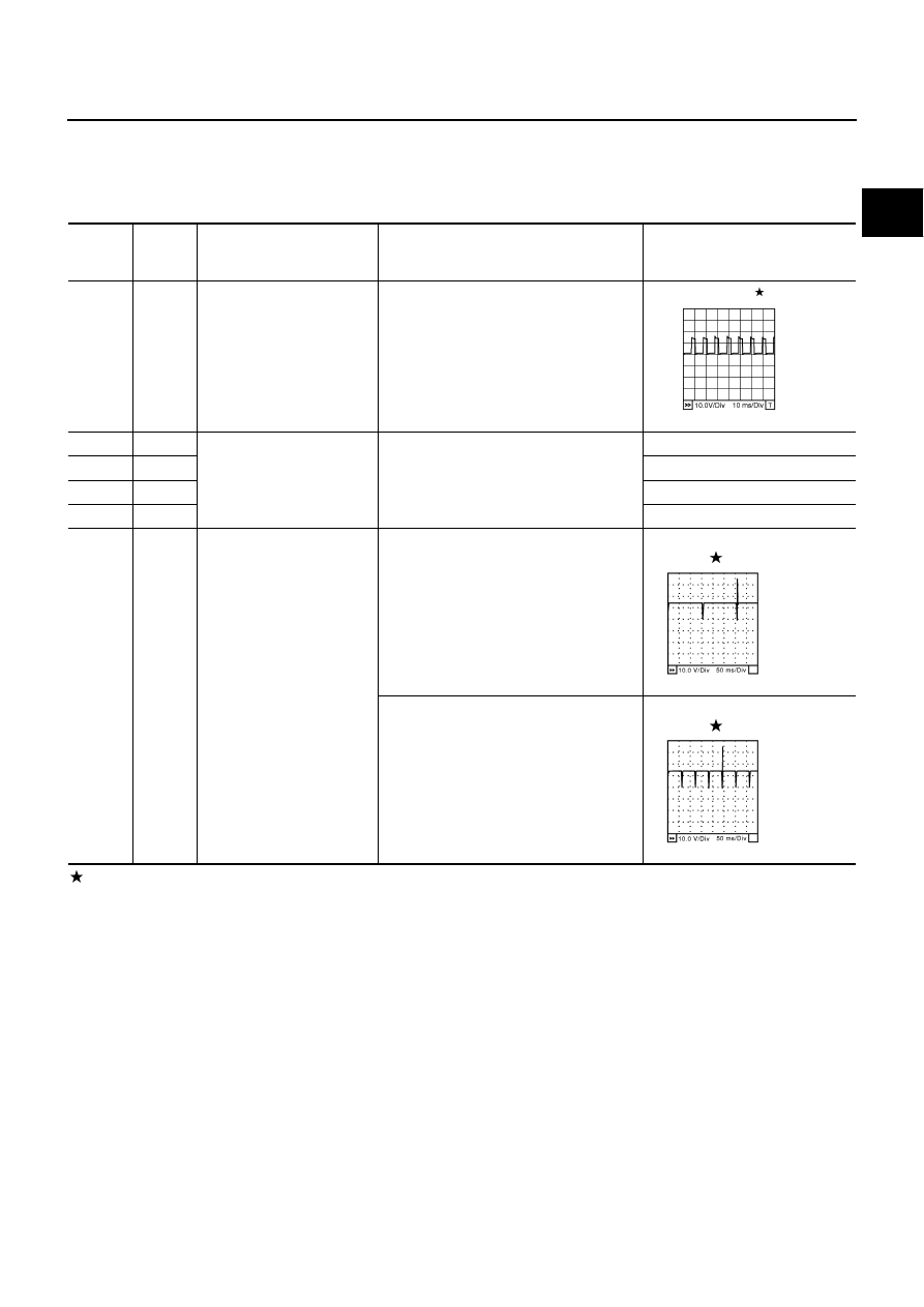
Fuel injector No. 5
Fuel injector No. 3
Fuel injector No. 1
[Engine is running]
●
Warm-up condition
●
Idle speed
NOTE:
The pulse cycle changes depending on
rpm at idle.
BATTERY VOLTAGE
(11 - 14V)
[Engine is running]
●
Warm-up condition
●
Engine speed: 2,000 rpm
BATTERY VOLTAGE
(11 - 14V)
PBIB1584E
SEC984C
SEC985C