Index Manuals Nissan Murano Z50 (2007 year) - Service and Repair Manual
Search copyright infringement
Content .. 61 62 63 64 ..
Nissan Murano Z50 (2007 year). Manual - part 63
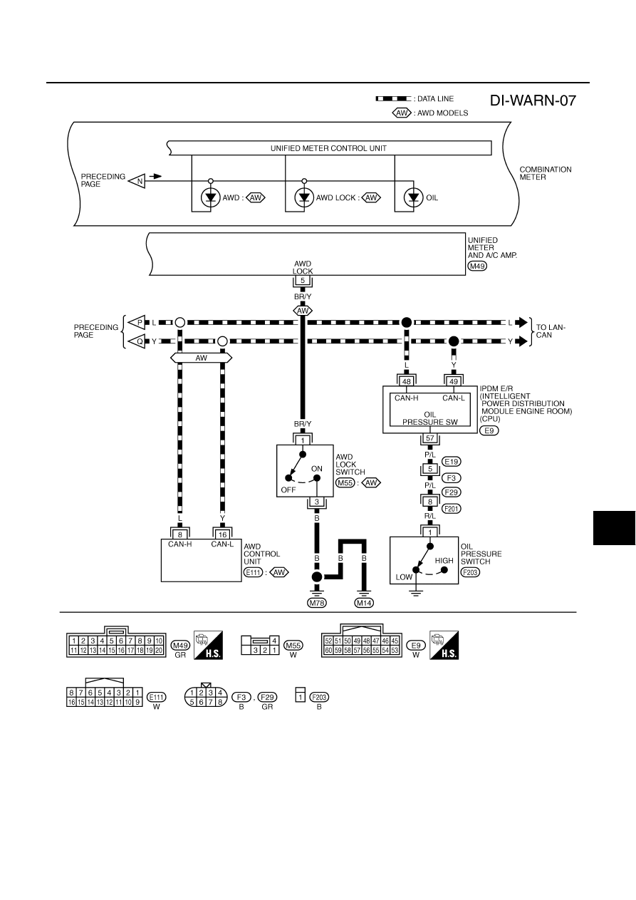
WARNING LAMPS
DI-45
C
D
E
F
G
H
I
J
L
M
A
B
DI
Revision: 2006 July
2007 Murano
TKWB2609E