Nissan Murano Z50 (2007 year). Manual - part 53
DTC P0744 A/T TCC S/V FUNCTION (LOCK-UP)
CVT-109
D
E
F
G
H
I
J
K
L
M
A
B
CVT
Revision: 2006 July
2007 Murano
DTC P0744 A/T TCC S/V FUNCTION (LOCK-UP)
PFP:31940
Description
NCS00157
This malfunction is detected when the torque converter clutch does not lock-up as instructed by the TCM. This
is not only caused by electrical malfunction (circuits open or shorted), but also by mechanical malfunction such
as control valve sticking, improper solenoid valve operation, etc.
CONSULT-II Reference Value
NCS00158
Remarks: Specification data are reference values.
On Board Diagnosis Logic
NCS00159
●
This is an OBD-II self-diagnostic item.
●
Diagnostic trouble code “P0744 A/T TCC S/V FNCTN” with CONSULT-II is detected under the following
conditions.
–
When CVT cannot perform lock-up even if electrical circuit is good.
–
When TCM compares difference value with slip revolution and detects an irregularity.
Possible Cause
NCS0015A
●
Torque converter clutch solenoid valve
●
Hydraulic control circuit
DTC Confirmation Procedure
NCS0015B
CAUTION:
Always drive vehicle at a safe speed.
NOTE:
If “DTC Confirmation Procedure” has been previously performed, always turn ignition switch OFF and
wait at least 10 seconds before performing the next test.
After the repair, touch “ERASE” on “SELF-DIAG RESULTS” and then perform the following procedure to con-
firm the malfunction is eliminated.
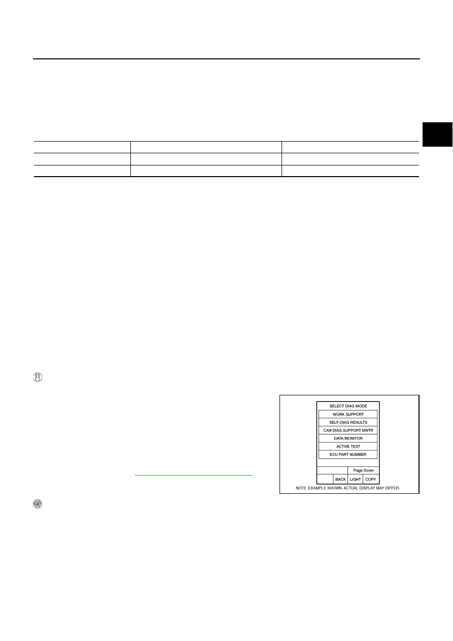
WITH CONSULT-II
1.
Turn ignition switch ON.
2.
Select “DATA MONITOR” mode for “TRANSMISSION” with
CONSULT-II.
3.
Start engine and maintain the following condition for at least 30
seconds.
ACC PEDAL OPEN: More than 1.0/8
RANGE: “D” position
[Vehicle speed: Constant speed of more than 40 km/h (25
MPH)]
4.
If DTC is detected go to
CVT-110, "Diagnostic Procedure"
.
WITH GST
Follow the procedure “WITH CONSULT-II”.
Item name
Condition
Display value
ENG SPEED SIG
Engine running
Closely matches the tachometer reading.
PRI SPEED SEN
During driving (lock-up ON)
Approximately matches the engine speed.
BCIA0031E