Nissan Murano Z50 (2007 year). Manual - part 48


  Index      Manuals     Nissan Murano Z50 (2007 year) - Service and Repair Manual


Search            copyright infringement  


Content      ..     46      47      48      49     ..


Nissan Murano Z50 (2007 year). Manual - part 48


ON BOARD DIAGNOSTIC (OBD) SYSTEM

CVT-29

D

E

F

G

H

I

J

K

L

M

A

B

CVT

Revision: 2006 July

2007 Murano

ON BOARD DIAGNOSTIC (OBD) SYSTEM

PFP:00028

Introduction

NCS0012Q

The CVT system has two self-diagnostic systems.
The first is the emission-related on board diagnostic system (OBD-II) performed by the TCM in combination
with the ECM. The malfunction is indicated by the MIL (malfunction indicator lamp) and is stored as a DTC in
the ECM memory, and the TCM memory.
The second is the TCM original self-diagnosis performed by the TCM. The malfunction is stored in the TCM
memory. The detected items are overlapped with OBD-II self-diagnostic items. For detail, refer to 

CVT-61,

"Display Items List"

 .

OBD-II Function for CVT System

NCS0012R

The ECM provides emission-related on board diagnostic (OBD-II) functions for the CVT system. One function
is to receive a signal from the TCM used with OBD-related parts of the CVT system. The signal is sent to the
ECM when a malfunction occurs in the corresponding OBD-related part. The other function is to indicate a
diagnostic result by means of the MIL (malfunction indicator lamp) on the instrument panel. Sensors, switches
and solenoid valves are used as sensing elements.
The MIL automatically illuminates in One or Two Trip Detection Logic when a malfunction is sensed in relation
to CVT system parts.

One or Two Trip Detection Logic of OBD-II

NCS0012S

ONE TRIP DETECTION LOGIC

If a malfunction is sensed during the first test drive, the MIL will illuminate and the malfunction will be stored in
the ECM memory as a DTC. The TCM is not provided with such a memory function.

TWO TRIP DETECTION LOGIC

When a malfunction is sensed during the first test drive, it is stored in the ECM memory as a 1st trip DTC
(diagnostic trouble code) or 1st trip freeze frame data. At this point, the MIL will not illuminate. — 1st trip
If the same malfunction as that experienced during the first test drive is sensed during the second test drive,
the MIL will illuminate. — 2nd trip
The “trip” in the “One or Two Trip Detection Logic” means a driving mode in which self-diagnosis is performed
during vehicle operation.

OBD-II Diagnostic Trouble Code (DTC)

NCS0012T

HOW TO READ DTC AND 1ST TRIP DTC

DTC and 1st trip DTC can be read by the following methods.
(

 with CONSULT-II or 

 GST) CONSULT-II or GST (Generic Scan Tool) Examples: P0705, P0720 etc.

These DTC are prescribed by SAE J2012.
(CONSULT-II also displays the malfunctioning component or system.)

1st trip DTC No. is the same as DTC No.

Output of the diagnostic trouble code indicates that the indicated circuit has a malfunction. How-
ever, in case of the Mode II and GST, they do not indicate whether the malfunction is still occurring
or occurred in the past and returned to normal.
CONSULT-II can identify them as shown below, therefore, CONSULT-II (if available) is recom-
mended.

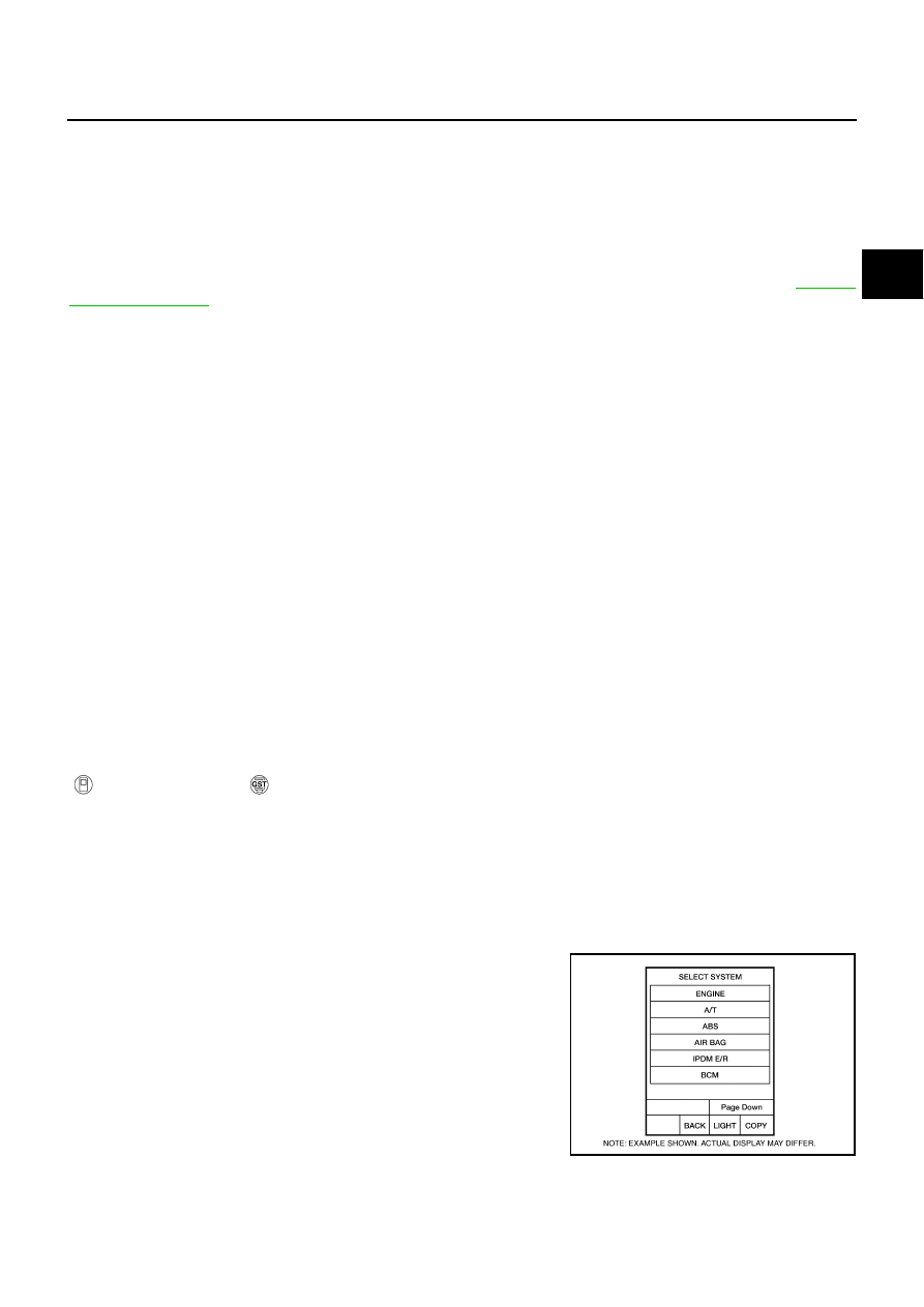
A sample of CONSULT-II display for DTC and 1st trip DTC is shown
on the next page. DTC or 1st trip DTC of a malfunction is displayed
in SELF-DIAGNOSTIC RESULTS mode for “ENGINE” with CON-
SULT-II. Time data indicates how many times the vehicle was driven
after the last detection of a DTC.

BCIA0030E

CVT-30

ON BOARD DIAGNOSTIC (OBD) SYSTEM

Revision: 2006 July

2007 Murano

If the DTC is being detected currently, the time data will be “0”.

If a 1st trip DTC is stored in the ECM, the time data will be “1t”.

Freeze Frame Data and 1st Trip Freeze Frame Data

The ECM has a memory function, which stores the driving condition such as fuel system status, calculated
load value, engine coolant temperature, short term fuel trim, long term fuel trim, engine speed and vehicle
speed at the moment the ECM detects a malfunction.
Data which are stored in the ECM memory, along with the 1st trip DTC, are called 1st trip freeze frame data,
and the data, stored together with the DTC data, are called freeze frame data and displayed on CONSULT-II
or GST. The 1st trip freeze frame data can only be displayed on the CONSULT-II screen, not on the GST. For
details, refer to 

EC-111, "CONSULT-II Function (ENGINE)"

 .

Only one set of freeze frame data (either 1st trip freeze frame data or freeze frame data) can be stored in the
ECM. 1st trip freeze frame data is stored in the ECM memory along with the 1st trip DTC. There is no priority
for 1st trip freeze frame data, and it is updated each time a different 1st trip DTC is detected. However, once
freeze frame data (2nd trip detection/MIL on) is stored in the ECM memory, 1st trip freeze frame data is no
longer stored. Remember, only one set of freeze frame data can be stored in the ECM. The ECM has the fol-
lowing priorities to update the data.

Both 1st trip freeze frame data and freeze frame data (along with the DTC) are cleared when the ECM mem-
ory is erased.

HOW TO ERASE DTC

The diagnostic trouble code can be erased by CONSULT-II, GST or ECM DIAGNOSTIC TEST MODE as
described following.

If the battery cable is disconnected, the diagnostic trouble code will be lost within 24 hours.

When you erase the DTC, using CONSULT-II or GST is easier and quicker than switching the mode
selector on the ECM.

The following emission-related diagnostic information is cleared from the ECM memory when erasing DTC
related to OBD-II. For details, refer to 

EC-46, "Emission-Related Diagnostic Information"

 .

Diagnostic trouble codes (DTC)

1st trip diagnostic trouble codes (1st trip DTC)

Freeze frame data

SAT015K

SAT016K

Priority

Items

1

Freeze frame data

Misfire — DTC: P0300 - P0306
Fuel Injection System Function — DTC: P0171, P0172, P0174, P0175

2

Except the above items (Includes CVT related items)

3

1st trip freeze frame data

ON BOARD DIAGNOSTIC (OBD) SYSTEM

CVT-31

D

E

F

G

H

I

J

K

L

M

A

B

CVT

Revision: 2006 July

2007 Murano

1st trip freeze frame data

System readiness test (SRT) codes

Test values

 HOW TO ERASE DTC (WITH CONSULT-II)

If a DTC is displayed for both ECM and TCM, it is necessary to be erased for both ECM and TCM.

1.

If the ignition switch stays ON after repair work, be sure to turn ignition switch OFF once. Wait at least 10
seconds and then turn it ON (engine stopped) again.

2.

Turn CONSULT-II ON and touch “TRANSMISSION”.

3.

Touch “SELF-DIAG RESULTS”.

4.

Touch “ERASE”. (The DTC in the TCM will be erased.) Then touch “BACK” twice.

5.

Touch “ENGINE”.

6.

Touch “SELF-DIAG RESULTS”.

7.

Touch “ERASE”. (The DTC in the ECM will be erased.)

 HOW TO ERASE DTC (WITH GST)

1.

If the ignition switch stays ON after repair work, be sure to turn ignition switch OFF once. Wait at least 10
seconds and then turn it ON (engine stopped) again.

2.

Select Mode 4 with GST (Generic Scan Tool). For details, refer to 

EC-123, "Generic Scan Tool (GST)

Function"

 .

SCIA7508E

CVT-32

ON BOARD DIAGNOSTIC (OBD) SYSTEM

Revision: 2006 July

2007 Murano

Malfunction Indicator Lamp (MIL)

NCS0012U

DESCRIPTION 

The MIL is located on the instrument panel.

1.

The MIL will light up when the ignition switch is turned ON with-
out the engine running. This is a bulb check.

If the MIL does not light up, refer to 

DI-37, "WARNING

LAMPS"

 , or see 

EC-662, "MIL AND DATA LINK CONNEC-

TOR"

 .

2.

When the engine is started, the MIL should go off.
If the MIL remains on, the on board diagnostic system has
detected an engine system malfunction.

SEF217U

TROUBLE DIAGNOSIS

CVT-33

D

E

F

G

H

I

J

K

L

M

A

B

CVT

Revision: 2006 July

2007 Murano

TROUBLE DIAGNOSIS

PFP:00004

DTC Inspection Priority Chart

NCS0012V

If some DTCs are displayed at the same time, perform inspections one by one based on the following priority
chart.
NOTE:
If DTC “U1000 CAN COMM CIRCUIT” is displayed with other DTCs, first perform the trouble diagnosis
for “DTC U1000 CAN COMMUNICATION LINE”. Refer to 

CVT-68

 .

Fail-safe

NCS0012W

The TCM has an electrical fail-safe mode. This mode makes it possible to operate even if there is an error in a
main electronic control input/output signal circuit. 

FAIL-SAFE FUNCTION 

If any malfunction occurs in a sensor or solenoid, this function controls the CVT to make driving possible.

Output Speed Sensor (Secondary Speed Sensor)

The shift pattern is changed in accordance with throttle position when an unexpected signal is sent from the
output speed sensor (secondary speed sensor) to the TCM. The manual mode position and second position is
inhibited, and the transaxle is put in “D”.

Input Speed Sensor (Primary Speed Sensor)

The shift pattern is changed in accordance with throttle position and secondary speed (vehicle speed) when
an unexpected signal is sent from the input speed sensor (primary speed sensor) to the TCM. The manual
mode position and second position is inhibited, and the transaxle is put in “D”.

PNP Switch

If an unexpected signal is sent from the PNP switch to the TCM, the transaxle is put in “D”. 

Manual Mode Switch

If an unexpected signal is sent from the manual mode switch to the TCM, the transaxle is put in “D”. 

CVT Fluid Temperature Sensor

If an unexpected signal is sent from the CVT fluid temperature sensor to the TCM, the gear ratio in use before
receiving the unexpected signal is maintained or the gear ratio is controlled to keep engine speed under 5000
rpm.

Transmission Fluid Pressure Sensor A (Secondary Pressure Sensor)

If an unexpected signal is sent from the transmission fluid pressure sensor A (secondary pressure sensor)
to the TCM, the secondary pressure feedback control is stopped and the offset value obtained before the
non-standard condition occurs is used to control line pressure.

If transmission fluid pressure sensor A (secondary pressure sensor) error signal is input to TCM, second-
ary pressure feedback control stops, but line pressure is controlled normally.

Pressure Control Solenoid A (Line Pressure Solenoid)

If an unexpected signal is sent from the solenoid to the TCM, the pressure control solenoid A (line pressure
solenoid) is turned OFF to achieve the maximum fluid pressure.

Pressure Control Solenoid B (Secondary Pressure Solenoid)

If an unexpected signal is sent from the solenoid to the TCM, the pressure control solenoid B (secondary pres-
sure solenoid) is turned OFF to achieve the maximum fluid pressure.

Torque Converter Clutch Solenoid

If an unexpected signal is sent from the solenoid to the TCM, the torque converter clutch solenoid is turned
OFF to cancel the lock-up.

Priority

Detected items (DTC)

1

U1000 CAN communication line

2

Except above

CVT-34

TROUBLE DIAGNOSIS

Revision: 2006 July

2007 Murano

Step Motor

If an unexpected signal is sent from the step motor to the TCM, the step motor coil phases “A” through “D” are
all turned OFF to hold the gear ratio used right before the non-standard condition occurred.

CVT Lock-up Select Solenoid

If an unexpected signal is sent from the solenoid to the TCM, the CVT lock-up select solenoid is turned OFF to
cancel the lock-up.

TCM Power Supply (Memory Back-up)

Transaxle assembly is protected by limiting the engine torque when the memory back-up power supply (for
controlling) from the battery is not supplied to TCM. Normal statues is restored when turning the ignition switch
OFF to ON after the normal power supply.

How to Perform Trouble Diagnosis for Quick and Accurate Repair

NCS0012X

INTRODUCTION

The TCM receives a signal from the vehicle speed sensor, PNP switch and provides shift control or lock-up
control via CVT solenoid valves.
The TCM also communicates with the ECM by means of a signal
sent from sensing elements used with the OBD-related parts of the
CVT system for malfunction-diagnostic purposes. The TCM is capa-
ble of diagnosing malfunctioning parts while the ECM can store mal-
functions in its memory.
Input and output signals must always be correct and stable in the
operation of the CVT system. The CVT system must be in good
operating condition and be free of valve seizure, solenoid valve mal-
function, etc.

It is much more difficult to diagnose an error that occurs intermit-
tently rather than continuously. Most intermittent errors are caused
by poor electric connections or improper wiring. In this case, careful
checking of suspected circuits may help prevent the replacement of
good parts.
A visual check only may not find the cause of the errors. A road test
with CONSULT-II (or GST) or a circuit tester connected should be
performed. Follow the 

CVT-35, "WORK FLOW"

 .

Before undertaking actual checks, take a few minutes to talk with a
customer who approaches with a driveability complaint. The cus-
tomer can supply good information about such errors, especially
intermittent ones. Find out what symptoms are present and under
what conditions they occur. A “DIAGNOSTIC WORKSHEET” as
shown on the example (Refer to 

CVT-36

 ) should be used.

Start your diagnosis by looking for “conventional” errors first. This will
help troubleshoot driveability errors on an electronically controlled
engine vehicle.
Also check related Service bulletins.

SAT631IB

SAT632I

SEF234G

TROUBLE DIAGNOSIS

CVT-35

D

E

F

G

H

I

J

K

L

M

A

B

CVT

Revision: 2006 July

2007 Murano

WORK FLOW

A good understanding of the malfunction conditions can make troubleshooting faster and more accurate.
In general, each customer feels differently about a malfunction. It is important to fully understand the symp-
toms or conditions for a customer complaint.
Make good use of the two sheets provided, 

CVT-36, "Information From Customer"

  and 

CVT-36, "Diagnostic

Worksheet Chart"

 , to perform the best troubleshooting possible.

Work Flow Chart

*1.

CVT-36

*2.

CVT-36

*3.

CVT-33

*4.

CVT-42

*5.

CVT-42

CVT-43

*6.

CVT-45

*7.

CVT-56

*8.

CVT-29

*9.

CVT-33

*10.

CVT-68

*11.

CVT-172

*12.

CVT-180

*13.

CVT-30

*14.

CVT-68

*15.

CVT-172

*16.

EC-46

SCIA6877E

CVT-36

TROUBLE DIAGNOSIS

Revision: 2006 July

2007 Murano

DIAGNOSTIC WORKSHEET
Information From Customer

KEY POINTS

WHAT..... Vehicle & CVT model

WHEN..... Date, Frequencies

WHERE..... Road conditions

HOW..... Operating conditions, Symptoms

Diagnostic Worksheet Chart

Customer name

MR/MS

Model & Year

VIN

Trans. Model

Engine

Mileage

malfunction Date

Manuf. Date

In Service Date

Frequency

 Continuous

 Intermittent (

times a day)

Symptoms

 Vehicle does not move.

(

 Any position

 Particular position)

 No shift

 Lock-up malfunction

 Shift shock or slip

(

 N 

 D

 N 

 R

 Lock-up

 Any drive position)

 Noise or vibration

 No pattern select

 Others

(

)

Malfunction indicator lamp (MIL)

 Continuously lit

 Not lit

1

 Read the item on cautions concerning fail-safe and understand the customer's complaint.

CVT-33

2

 CVT fluid inspection

CVT-42

 Leak (Repair leak location.)

 State

 Amount

3

 Stall test and line pressure test

CVT-42

CVT-43

 Stall test

 Torque converter one-way clutch

 Reverse brake

 Forward clutch

 Steel belt

 Engine

 Line pressure low

 Primary pulley

 Secondary pulley

 Line pressure inspection - Suspected part:

TROUBLE DIAGNOSIS

CVT-37

D

E

F

G

H

I

J

K

L

M

A

B

CVT

Revision: 2006 July

2007 Murano

4

 Perform road test.

CVT-45

4-1.

Check before engine is started 

CVT-47


CVT-184, "CVT Indicator Lamp Does Not Come On"

 Perform self-diagnosis. Enter checks for detected items. 

CVT-61


CVT-68, "DTC U1000 CAN COMMUNICATION LINE"


CVT-71, "DTC P0615 START SIGNAL CIRCUIT"


CVT-75, "DTC P0703 STOP LAMP SWITCH CIRCUIT"


CVT-77, "DTC P0705 PARK/NEUTRAL POSITION SWITCH"


CVT-84, "DTC P0710 CVT FLUID TEMPERATURE SENSOR CIRCUIT"


CVT-89, "DTC P0715 INPUT SPEED SENSOR CIRCUIT (PRI SPEED SENSOR)"


CVT-94, "DTC P0720 VEHICLE SPEED SENSOR CVT (SECONDARY SPEED 

SENSOR)"


CVT-100, "DTC P0725 ENGINE SPEED SIGNAL"


CVT-102, "DTC P0730 BELT DAMAGE"


CVT-104, "DTC P0740 TORQUE CONVERTER CLUTCH SOLENOID VALVE"


CVT-109, "DTC P0744 A/T TCC S/V FUNCTION (LOCK-UP)"


CVT-112, "DTC P0745 LINE PRESSURE SOLENOID VALVE"


CVT-117, "DTC P0746 PRESSURE CONTROL SOLENOID A PERFORMANCE 

(LINE PRESSURE SOLENOID VALVE)"


CVT-120, "DTC P0776 PRESSURE CONTROL SOLENOID B PERFORMANCE 

(SEC PRESSURE SOLENOID VALVE)"


CVT-123, "DTC P0778 PRESSURE CONTROL SOLENOID B ELECTRICAL (SEC 

PRESSURE SOLENOID VALVE)"


CVT-128, "DTC P0826 MANUAL MODE SWITCH CIRCUIT"


CVT-133, "DTC P0840 TRANSMISSION FLUID PRESSURE SENSOR A CIRCUIT 

(SEC PRESSURE SENSOR)"


CVT-138, "DTC P0841 PRESSURE SENSOR FUNCTION"


CVT-141, "DTC P0845 TRANSMISSION FLUID PRESSURE SENSOR B CIRCUIT 

(PRI PRESSURE SENSOR)"


CVT-146, "DTC P0868 SECONDARY PRESSURE DOWN"


CVT-149, "DTC P1701 TRANSMISSION CONTROL MODULE (POWER SUPPLY)"


CVT-154, "DTC P1705 THROTTLE POSITION SENSOR"


CVT-156, "DTC P1722 ESTM VEHICLE SPEED SIGNAL"


CVT-158, "DTC P1723 CVT SPEED SENSOR FUNCTION"


CVT-160, "DTC P1726 ELECTRIC THROTTLE CONTROL SYSTEM"


CVT-162, "DTC P1740 LOCK-UP SELECT SOLENOID VALVE CIRCUIT"


CVT-168, "DTC P1777 STEP MOTOR - CIRCUIT"


CVT-172, "DTC P1778 STEP MOTOR - FUNCTION"

4-2.

Check at idle

CVT-47


CVT-185, "Engine Cannot Be Started in “P” and “N” Position"


CVT-186, "In “P” Position, Vehicle Moves Forward or Backward When Pushed"


CVT-186, "In “N” Position, Vehicle Moves"


CVT-187, "Large Shock “N” 

 “R” Position"


CVT-188, "Vehicle Does Not Creep Backward in “R” Position"


CVT-190, "Vehicle Does Not Creep Forward in “D”, “S” or “L” Position"

CVT-38

TROUBLE DIAGNOSIS

Revision: 2006 July

2007 Murano

4

4-3.

Cruise test

CVT-49


CVT-191, "CVT Does Not Shift"


CVT-192, "Cannot Be Changed to Manual Mode"


CVT-193, "CVT Does Not Shift in Manual Mode"


CVT-194, "Cannot Be Changed to Second Position (Without Manual Mode)"


CVT-195, "Cannot Be Changed to “L” Position (Without Manual Mode)"


CVT-196, "Vehicle Does Not Decelerate by Engine Brake"

 perform self-diagnosis. Enter checks for detected items. 

CVT-61


CVT-68, "DTC U1000 CAN COMMUNICATION LINE"


CVT-71, "DTC P0615 START SIGNAL CIRCUIT"


CVT-75, "DTC P0703 STOP LAMP SWITCH CIRCUIT"


CVT-77, "DTC P0705 PARK/NEUTRAL POSITION SWITCH"


CVT-84, "DTC P0710 CVT FLUID TEMPERATURE SENSOR CIRCUIT"


CVT-89, "DTC P0715 INPUT SPEED SENSOR CIRCUIT (PRI SPEED SENSOR)"


CVT-94, "DTC P0720 VEHICLE SPEED SENSOR CVT (SECONDARY SPEED 

SENSOR)"


CVT-100, "DTC P0725 ENGINE SPEED SIGNAL"


CVT-102, "DTC P0730 BELT DAMAGE"


CVT-104, "DTC P0740 TORQUE CONVERTER CLUTCH SOLENOID VALVE"


CVT-109, "DTC P0744 A/T TCC S/V FUNCTION (LOCK-UP)"


CVT-112, "DTC P0745 LINE PRESSURE SOLENOID VALVE"


CVT-117, "DTC P0746 PRESSURE CONTROL SOLENOID A PERFORMANCE 

(LINE PRESSURE SOLENOID VALVE)"


CVT-120, "DTC P0776 PRESSURE CONTROL SOLENOID B PERFORMANCE 

(SEC PRESSURE SOLENOID VALVE)"


CVT-123, "DTC P0778 PRESSURE CONTROL SOLENOID B ELECTRICAL (SEC 

PRESSURE SOLENOID VALVE)"


CVT-128, "DTC P0826 MANUAL MODE SWITCH CIRCUIT"


CVT-133, "DTC P0840 TRANSMISSION FLUID PRESSURE SENSOR A CIRCUIT 

(SEC PRESSURE SENSOR)"


CVT-138, "DTC P0841 PRESSURE SENSOR FUNCTION"


CVT-141, "DTC P0845 TRANSMISSION FLUID PRESSURE SENSOR B CIRCUIT 

(PRI PRESSURE SENSOR)"


CVT-146, "DTC P0868 SECONDARY PRESSURE DOWN"


CVT-149, "DTC P1701 TRANSMISSION CONTROL MODULE (POWER SUPPLY)"


CVT-154, "DTC P1705 THROTTLE POSITION SENSOR"


CVT-156, "DTC P1722 ESTM VEHICLE SPEED SIGNAL"


CVT-158, "DTC P1723 CVT SPEED SENSOR FUNCTION"


CVT-160, "DTC P1726 ELECTRIC THROTTLE CONTROL SYSTEM"


CVT-162, "DTC P1740 LOCK-UP SELECT SOLENOID VALVE CIRCUIT"


CVT-168, "DTC P1777 STEP MOTOR - CIRCUIT"


CVT-172, "DTC P1778 STEP MOTOR - FUNCTION"

5

 Inspect each system for items found to be NG in the self-diagnosis and repair or replace the malfunctioning parts.

6

 Perform all road tests and enter the checks again for the required items.

CVT-45

7

 For any remaining NG items, perform the “diagnosis procedure” and repair or replace the malfunctioning parts.

8

 Erase the results of the self-diagnosis from the TCM.

CVT-31

CVT-31

TROUBLE DIAGNOSIS

CVT-39

D

E

F

G

H

I

J

K

L

M

A

B

CVT

Revision: 2006 July

2007 Murano

CVT Electrical Parts Location (With Manual Mode)

NCS0012Y

SCIA8103E

CVT-40

TROUBLE DIAGNOSIS

Revision: 2006 July

2007 Murano

CVT Electrical Parts Location (Without Manual Mode)

NCS0012Z

SCIA8104E

TROUBLE DIAGNOSIS

CVT-41

D

E

F

G

H

I

J

K

L

M

A

B

CVT

Revision: 2006 July

2007 Murano

Circuit Diagram

NCS00130

TCWB0258E

CVT-42

TROUBLE DIAGNOSIS

Revision: 2006 July

2007 Murano

Inspections before Trouble Diagnosis

NCS00131

CVT FLUID CHECK
Fluid Leakage and Fluid Level Check 

Inspect for fluid leakage and check the fluid level. Refer to 

CVT-15, "Checking CVT Fluid"

 .

Fluid Condition Check

Inspect the fluid condition.

STALL TEST
Stall Test Procedure

1.

Inspect the amount of engine oil. Replenish the engine oil if necessary.

2.

Drive for about 10 minutes to warm up the vehicle so that the
CVT fluid temperature is 50 to 80

°

C (122 to 176

°

F). Inspect the

amount of CVT fluid. Replenish if necessary.

3.

Securely engage the parking brake so that the tires do not turn.

4.

Install a tachometer where it can be seen by driver during test.

It is good practice to mark the point of specified engine
rpm on indicator.

5.

Start engine, apply foot brake, and place selector lever in “D”
position.

6.

While holding down the foot brake, gradually press down the
accelerator pedal.

7.

Quickly read off the stall speed, and then quickly remove your
foot from the accelerator pedal.

CAUTION:

Do not hold down the accelerator pedal for more than 5 sec-
onds during this test.

8.

Move the selector lever to the “N” position.

Fluid status

Conceivable cause

Required operation

Varnished (viscous 
varnish state)

Clutch, brake 
scorched

Replace the CVT fluid and check 
the CVT main unit and the vehicle 
for malfunctions (wire harnesses, 
cooler pipes, etc.)

Milky white or 
cloudy

Water in the fluid

Replace the CVT fluid and check for 
places where water is getting in.

Large amount of 
metal powder mixed 
in

Unusual wear of 
sliding parts within 
CVT

Replace the CVT fluid and check for 
improper operation of the CVT.

SAT638A

SAT647B

SCIA7463E

Stall speed:

2,700 – 3,250 rpm

SAT514G

TROUBLE DIAGNOSIS

CVT-43

D

E

F

G

H

I

J

K

L

M

A

B

CVT

Revision: 2006 July

2007 Murano

9.

Cool down the CVT fluid.

CAUTION:

Run the engine at idle for at least 1 minute.

10. Repeat steps 6 through 9 with selector lever in “R” position.

Judgment Stall Test

O: Stall speed within standard value position.
H: Stall speed is higher than standard value.
L: Stall speed is lower than standard value.

LINE PRESSURE TEST
Line Pressure Test Port

Line Pressure Test Procedure

1.

Inspect the amount of engine oil and replenish if necessary.

2.

Drive the car for about 10 minutes to warm it up so that the CVT fluid reaches in the range of 50 to 80

°

C

(122 to 176

°

F), then inspect the amount of CVT fluid and replenish if necessary.

NOTE:
The CVT fluid temperature rises in the range of 50 to 80

°

C (122 to 176

°

F) during 10 minutes of driv-

ing.

3.

After warming up CVT, remove the oil pressure detection plug and install the oil pressure gauge [special
service tool: — (OTC3492)].

CAUTION:

When using the oil pressure gauge, be sure to use the O-ring attached to the oil pressure detec-
tion plug.

4.

Securely engage the parking brake so that the tires do not turn.

Selector lever position

Expected problem location

“D”

“R”

Stall rotation 

H

O

Forward clutch

O

H

Reverse brake

L

L

Engine and torque converter one-way clutch

H

H

Line pressure low

Primary pulley

Secondary pulley

Steel belt

SCIA1980E

SCIA7463E

CVT-44

TROUBLE DIAGNOSIS

Revision: 2006 July

2007 Murano

5.

Start the engine, and then measure the line pressure at both idle
and the stall speed.

CAUTION:

Keep the brake pedal pressed all the way down during
measurement.

When measuring the line pressure at the stall speed,
refer to 

CVT-42, "STALL TEST"

 . 

6.

After the measurements are complete, install the oil pressure
detection plug and tighten to the specified torque below.

CAUTION:

Do not reuse O-ring.

Apply CVT fluid to O-ring.

Line Pressure

*

1

 : Without manual mode

*

2

 : Reference values

Judgment of Line Pressure Test

: 7.5 N·m (0.77 kg-m, 66 in-lb)

SAT493G

Engine speed

 Line pressure

kPa (kg/cm

2

 , psi)

“R”, “D” and “L”*

1

  positions

At idle

750 (7.65, 108.8)

At stall

5,700 (58.14, 826.5)*

2

Judgment Possible 

cause

Idle speed

Low for all positions 
(“P”, “R”, “N”, “D”, 
“L”*)

Possible causes include malfunctions in the pressure supply system and low oil pump output.
For example

Oil pump wear

Pressure regulator valve or plug sticking or spring fatigue

Oil strainer 

Þ

 oil pump 

Þ

 pressure regulator valve passage oil leak

Engine idle speed too low

Only low for a spe-
cific position

Possible causes include an oil pressure leak in a passage or device related to the position after 
the pressure is distributed by the manual valve.

High

Possible causes include a sensor malfunction or malfunction in the line pressure adjustment func-
tion.
For example

Accelerator pedal position signal malfunction

CVT fluid temperature sensor malfunction

Pressure control solenoid A (line pressure solenoid) malfunction (sticking in OFF state, filter 
clog, cut line)

Pressure regulator valve or plug sticking


Content      ..     46      47      48      49     ..