Nissan Murano Z50 (2007 year). Manual - part 44
ACTUATOR AND ELECTRIC UNIT (ASSEMBLY)
BRC-99
[VDC/TCS/ABS]
C
D
E
G
H
I
J
K
L
M
A
B
BRC
Revision: 2006 July
2007 Murano
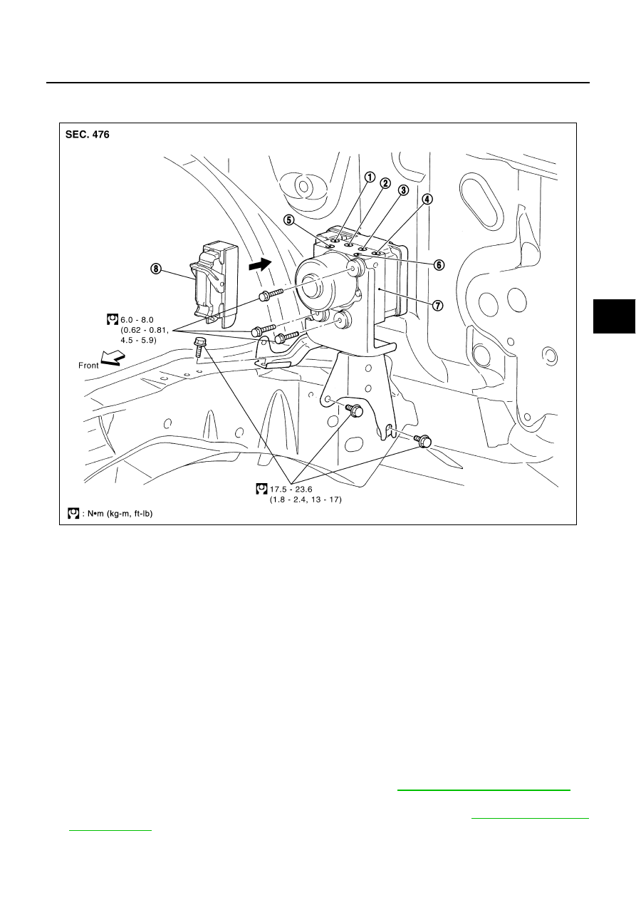
ACTUATOR AND ELECTRIC UNIT (ASSEMBLY)
PFP:47660
Removal and Installation
NFS000HA
Pay attention to the following when removing actuator.
CAUTION:
●
If the part number on the part number label (pasted on actuator upper surface) is the same, ABS
actuator and electric unit (control unit) (integrated in control unit, part No.: 47660 *****) can not be
used on another vehicle.
If it is used on another vehicle, ABS warning lamp, SLIP indicator lamp, VDC OFF indicator lamp
may turn ON or VDC/TCS/ABS may not operate normally.
When replacing ABS actuator and electric unit (control unit) (integrated in control unit), must use
new service parts.
●
Before servicing, disconnect battery cables.
●
To remove brake tube, use flare nut torque wrench to prevent flare nuts and brake tube from being
damaged. To install, use flare nut wrench (commercial service tool).
●
Do not remove and install actuator by holding harness.
●
After work is completed, bleed air from brake piping. Refer to
BR-13, "Bleeding Brake System"
.
NOTE:
●
After performing above works, calibrate decel G sensor (AWD model). Refer to
.
PFIA0800E
1.
To front left
2.
To rear right
3.
To rear left
4.
To front right
5.
From master cylinder secondary
side
6.
From master cylinder primary side
7.
ABS actuator and electric unit (con-
trol unit)
8.
Harness connector