Nissan Murano Z50 (2007 year). Manual - part 43
TROUBLE DIAGNOSIS FOR SYSTEM
BRC-83
[VDC/TCS/ABS]
C
D
E
G
H
I
J
K
L
M
A
B
BRC
Revision: 2006 July
2007 Murano
Solenoid and VDC Change-Over Valve
NFS000GR
INSPECTION PROCEDURE
1.
CHECK SELF-DIAGNOSTIC RESULTS
Check self-diagnostic results.
Is above displayed in the self-diagnosis display?
YES
>> GO TO 2.
NO
>> INSPECTION END
2.
CHECK CONNECTOR
1.
Turn ignition switch “OFF”.
2.
Disconnect ABS actuator and electric unit (control unit) connector E24 check terminals for deformation,
disconnection, looseness, and so on. If there is an error, repair or replace terminal.
3.
Reconnect connectors and then perform the self-diagnosis.
OK or NG
OK
>> INSPECTION END.
NG
>> GO TO 3.
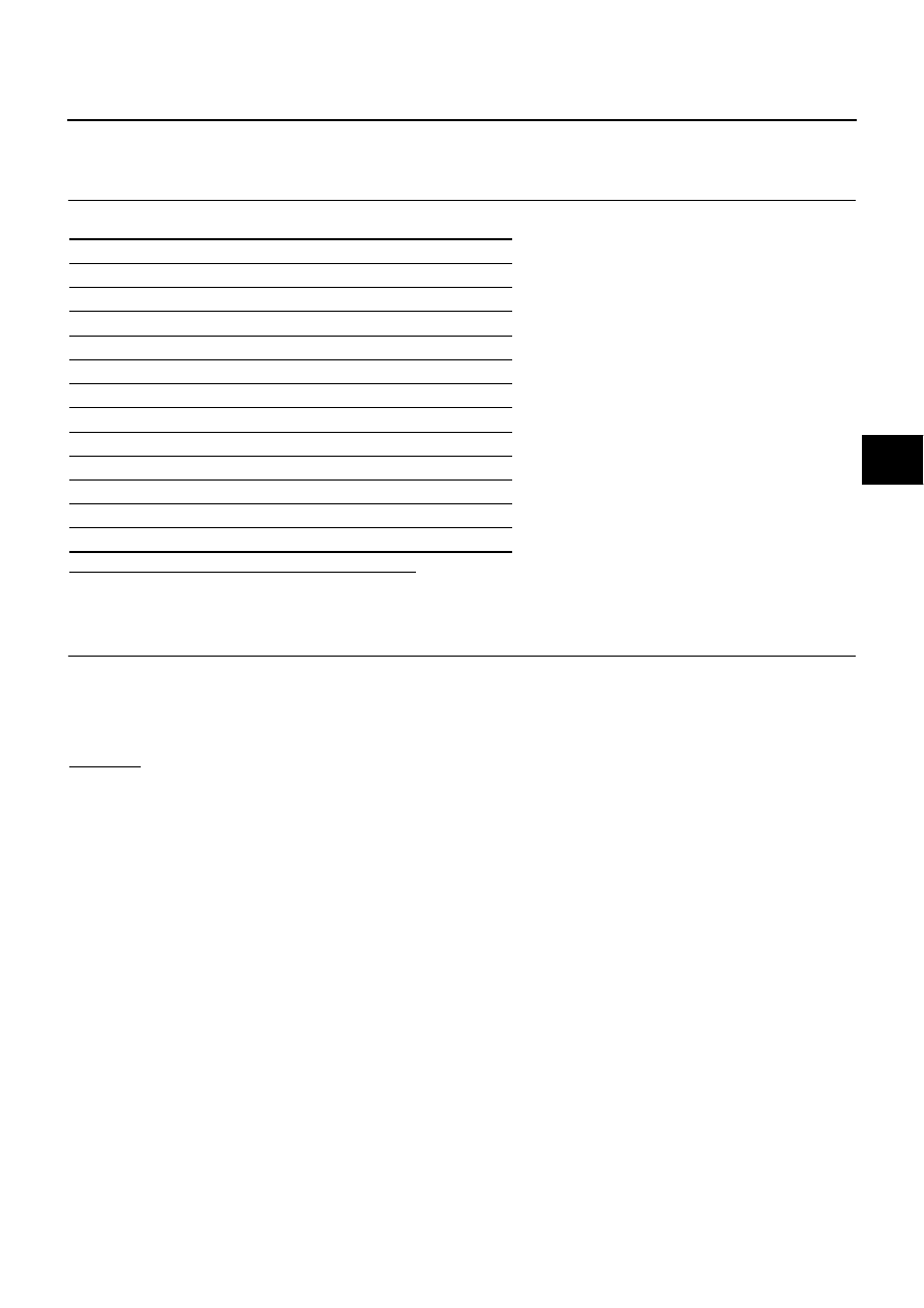
Self-diagnostic results
FR LH IN SOL
FR LH OUT SOL
RR RH IN SOL
RR RH OUT SOL
FR RH IN SOL
FR RH OUT SOL
RR LH IN SOL
RR LH OUT SOL
CV 1
CV 2
SV 1
SV 2