Nissan Murano Z50 (2007 year). Manual - part 41


  Index      Manuals     Nissan Murano Z50 (2007 year) - Service and Repair Manual


Search            copyright infringement  


Content      ..     39      40      41      42     ..


Nissan Murano Z50 (2007 year). Manual - part 41


TROUBLE DIAGNOSIS

BRC-51

[VDC/TCS/ABS]

C

D

E

G

H

I

J

K

L

M

A

B

BRC

Revision: 2006 July

2007 Murano

TROUBLE DIAGNOSIS

PFP:00004

Fail-Safe Function

NFS000LE

VDC/TCS SYSTEM

In case of malfunction with TCS, the VDC OFF indicator lamp and SLIP indicator lamp are turned on, and the
condition of the vehicle is the same as the condition of vehicles without VDC/TCS system. In case of malfunc-
tion with TCS, the ABS control continues to operate normally without VDC/TCS control.

CAUTION:

If the Fail-Safe function is activated, then perform the Self Diagnosis for VDC/TCS/ABS control sys-
tem.

ABS, EBD SYSTEM

In case of electrical malfunction with the ABS, the ABS warning lamp, VDC OFF indicator lamp and SLIP indi-
cator lamp will turn on. In case of electrical malfunction with the EBD, Brake warning lamp, ABS warning lamp,
VDC OFF indicator lamp and SLIP indicator lamp will turn on. Simultaneously, the VDC/TCS/ABS become one
of the following conditions of the Fail- Safe function.

For ABS malfunction, only the EBD is activated and the condition of the vehicle is the same condition of
vehicles without TCS/ABS system.

NOTE:
ABS self-diagnosis sound may be heard. That is a normal condition because a self-diagnosis for “Ignition
switch ON” and “The first starting” are being performed.

For EBD malfunction, the EBD and ABS become inoperative, and the condition of the vehicle is the same
as the condition of vehicles without VDC/TCS/ABS, EBD system.

How to Perform Trouble Diagnosis for Quick and Accurate Repair

NFS000GD

INTRODUCTION

Most important point to perform diagnosis is to understand systems (control and mechanism) in vehicle
thoroughly.

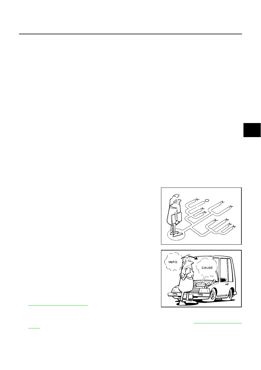
It is also important to clarify customer complaints before inspec-
tion.
First of all, reproduce symptom, and understand it fully.
Ask customer about his/her complaints carefully. In some cases,
it will be necessary to check symptom by driving vehicle with
customer.

NOTE:
Customers are not professionals. Do not assume “maybe cus-
tomer means...” or “maybe customer mentioned this symptom”.

It is essential to check symptoms right from beginning in order to
repair a malfunction completely.
For an intermittent malfunction, it is important to reproduce
symptom based on interview with customer and past examples.
Do not perform inspection on ad hoc basis. Most intermittent
malfunctions are caused by poor contacts. In this case, it will be
effective to shake suspected harness or connector by hand.
When repairs are performed without any symptom check, no
one can judge if malfunction has actually been eliminated.

After diagnosis, make sure to perform “erase memory”. Refer to

BRC-67, "ERASE MEMORY"

 .

For an intermittent malfunction, move harness or harness con-
nector by hand to check poor contact or false open circuit.

Always read “GI General Information” to confirm general precautions. Refer to 

GI-4, "General Precau-

tions"

 . 

EFJ0028D

SEF233G

BRC-52

[VDC/TCS/ABS]

TROUBLE DIAGNOSIS

Revision: 2006 July

2007 Murano

DIAGNOSIS FLOW CHART

SFIA3272E

TROUBLE DIAGNOSIS

BRC-53

[VDC/TCS/ABS]

C

D

E

G

H

I

J

K

L

M

A

B

BRC

Revision: 2006 July

2007 Murano

ASKING COMPLAINTS

Complaints against malfunction vary depending on each person.
It is important to clarify customer complaints.

Ask customer about what symptoms are present and under
what conditions. Use information to reproduce symptom while
driving.

It is also important to use the diagnosis sheet so as not to miss
information.

EXAMPLE OF DIAGNOSIS SHEET

SBR339B

SFIA3264E

BRC-54

[VDC/TCS/ABS]

TROUBLE DIAGNOSIS

Revision: 2006 July

2007 Murano

Component Installation Location

NFS000GE

PFIA0744E

TROUBLE DIAGNOSIS

BRC-55

[VDC/TCS/ABS]

C

D

E

G

H

I

J

K

L

M

A

B

BRC

Revision: 2006 July

2007 Murano

Schematic

NFS000GF

TFWB0118E

BRC-56

[VDC/TCS/ABS]

TROUBLE DIAGNOSIS

Revision: 2006 July

2007 Murano

Wiring Diagram — VDC —

NFS000GG

TFWB0119E

TROUBLE DIAGNOSIS

BRC-57

[VDC/TCS/ABS]

C

D

E

G

H

I

J

K

L

M

A

B

BRC

Revision: 2006 July

2007 Murano

TFWB0038E

BRC-58

[VDC/TCS/ABS]

TROUBLE DIAGNOSIS

Revision: 2006 July

2007 Murano

TFWB0039E

TROUBLE DIAGNOSIS

BRC-59

[VDC/TCS/ABS]

C

D

E

G

H

I

J

K

L

M

A

B

BRC

Revision: 2006 July

2007 Murano

TFWA0069E

BRC-60

[VDC/TCS/ABS]

TROUBLE DIAGNOSIS

Revision: 2006 July

2007 Murano

TFWB0040E

TROUBLE DIAGNOSIS

BRC-61

[VDC/TCS/ABS]

C

D

E

G

H

I

J

K

L

M

A

B

BRC

Revision: 2006 July

2007 Murano

TFWB0120E

BRC-62

[VDC/TCS/ABS]

TROUBLE DIAGNOSIS

Revision: 2006 July

2007 Murano

Control Unit Input/Output Signal Standard

NFS000GH

REFERENCE VALUE FROM CONSULT-II

CAUTION:

The display shows the control unit calculation data, so a normal value might be displayed even in the
event the output circuit (harness) is open or short - circuited.

Monitor item

Display content

Data monitor

Condition

Reference value in 

normal operation

SLCT LVR POSI

Select shift position

CVT shift position = P, R, D, L, N posi-
tion

Display selected shift 
position one of P, R, D, 
L, and N.

S position

##

FR RH SENSOR
FR LH SENSOR
RR RH SENSOR
RR LH SENSOR

Wheel speed

Vehicle stopped

0 [km/h (MPH)]

Vehicle running (Note 1)

Almost in accordance 
with speedometer dis-
play (within 

±

 10%)

ACCEL POS SIG 

Open/close condition of throttle valve 
(linked with accelerator pedal).

Accelerator pedal not depressed
(Engine stopped)

0%

Depress accelerator pedal
(Engine stopped)

0 - 100%

ENGINE SPEED

With engine running

With engine stopped

0 rpm

Engine running

Almost in accordance 
with tachometer dis-
play

STR ANGLE SIG

Steering angle detected by steering angle 
sensor

Straight-ahead

Approx. 0

°

Steering wheel turned

–756 - 756

°

YAW RATE SEN

Yaw rate detected by yaw rate/side decel G 
sensor

Vehicle stopped

Approx. 0 d/s

Vehicle running

–100 - 100 d/s

SIDE G SENSOR

Transverse G detected by yaw rate/side 
decel G sensor

Vehicle stopped

Approx. 0 m/s

2

Vehicle running

–16.7 - 16.7 m/s

2

PRESS SENSOR

Brake fluid pressure detected by pressure 
sensor

With ignition switch turned ON and 
brake pedal released

Approx. 0 bar

With ignition switch turned ON and 
brake pedal depressed

 0 to 170 bar

BATTERY VOLT

Battery voltage supplied to ABS actuator 
and electric unit (control unit)

Ignition switch ON

10 - 16 V

STOP LAMP SW

Brake pedal operation

Brake pedal depressed

ON

Brake pedal not depressed

OFF

OFF SW

VDC OFF switch ON/OFF status 

VDC OFF switch ON
(When VDC OFF indicator lamp is 
ON)

ON

VDC OFF switch OFF
(When VDC OFF indicator lamp is 
OFF)

OFF

ABS WARN LAMP

ABS warning lamp ON condition (Note 2)

ABS warning lamp ON

ON

ABS warning lamp OFF

OFF

MOTOR RELAY

Operation status of motor and motor relay

Ignition switch ON or engine running 
(ABS not operated)

OFF

Ignition switch ON or engine running 
(ABS operated)

ON

ACTUATOR RLY

Actuator relay operation status

Vehicle stopped (Ignition switch ON)

OFF

Vehicle stopped (Engine running)

ON

TROUBLE DIAGNOSIS

BRC-63

[VDC/TCS/ABS]

C

D

E

G

H

I

J

K

L

M

A

B

BRC

Revision: 2006 July

2007 Murano

OFF LAMP

VDC OFF indicator lamp status (Note 3) 

When VDC OFF indicator lamp is ON

ON

When VDC OFF indicator lamp is 
OFF

OFF

SLIP LAMP

SLIP indicator lamp status (Note 4)

When SLIP indicator lamp is ON

ON

When SLIP indicator lamp is blinking

When SLIP indicator lamp is OFF

OFF

FR LH IN SOL
FR LH OUT SOL
FR RH IN SOL
FR RH OUT SOL
RR RH IN SOL
RR RH OUT SOL
RR LH IN SOL
RR LH OUT SOL

Solenoid valve operation

Actuator (solenoid) is active (“ACTIVE 
TEST” with CONSULT-II) or actuator 
relay is inactive (in fail-safe mode).

ON

When actuator (solenoid) is not active 
and actuator relay is active (ignition 
switch ON).

OFF

CV1
CV2
SV1
SV2

VDC/TCS switch-over valve status

When actuator (switch-over valve) is 
active (“ACTIVE TEST” with CON-
SULT-II) or actuator relay is inactive 
(when in fail-safe mode).

ON

When actuator (switch-over valve) is 
not active and actuator relay is active 
(ignition switch ON).

OFF

DECEL G-SEN

Longitudinal acceleration detected by decel 
G Sensor (Note5)

Vehicle stopped

Approx. 0G

Vehicle running

-1.7 - +1.7G

FLUID LEV SW

ON/OFF status of brake fluid level switch

When brake fluid level switch ON

ON

When brake fluid level switch OFF 

OFF

VDC FAIL SIG
TCS FAIL SIG
ABS FAIL SIG
EBD FAIL SIG

Fail signal status

VDC fail
TCS fail
ABS fail
EBD fail

ON

VDC normal
TCS normal
ABS normal
EBD normal

OFF

EBD WARN LAMP

Brake warning lamp on condition (Note 6)

Brake warning lamp ON

ON

Brake warning lamp OFF

OFF

EBD SIGNAL

EBD operation

EBD active

ON

EBD not active

OFF

ABS SIGNAL

ABS operation

ABS active

ON

ABS not active

OFF

TCS SIGNAL

TCS operation

TCS active

ON

TCS not active

OFF

VDC SIGNAL

VDC operation

VDC active

ON

VDC not active

OFF

CRANKING SIG

CRANKING status

Cranking

ON

Not cranking

OFF

4WD FAIL REQ

ETS fail status (Note 5)

ETS fail

ON

ETS normal

OFF

2WD/4WD

Drive axle

2WD model

2WD

AWD model

4WD

Monitor item

Display content

Data monitor

Condition

Reference value in 

normal operation

BRC-64

[VDC/TCS/ABS]

TROUBLE DIAGNOSIS

Revision: 2006 July

2007 Murano

Note 1: Confirm tire pressure is normal.
Note 2: ON/OFF timing of ABS warning lamp
ON: After ignition switch is turned ON, or when a malfunction is detected.
OFF: After ignition switch is turned ON (when system is in normal operation) condition by VDC.
Note 3: ON/OFF timing of VDC OFF indicator lamp
ON: After ignition switch is turned ON, or when a malfunction is detected and VDC OFF switch is ON.
OFF: After ignition switch is turned ON (when system is in normal operation.) And when VDC OFF switch is OFF.
Note 4: ON/OFF timing of SLIP indicator lamp
ON: After ignition switch is turned ON, or when a malfunction is detected.
OFF: After ignition switch is turned ON (when system is in normal operation) and VDC/TCS function is not activated.
Blinking: VDC/TCS function is active during driving
Note 5: Only AWD models.
Note 6: Serves as EBD warning lamp.

CONSULT-II Functions (ABS)

NFS000GI

CONSULT-II MAIN FUNCTION 

CONSULT-II can display each diagnostic item using the diagnostic test modes shown following.

CONSULT-II SETTING PROCEDURE

Refer to 

GI-37, "CONSULT-II Start Procedure"

 .

Diagnostic test mode

Function

Reference

WORK SUPPORT

This mode enables a technician to adjust some devices faster and more accu-
rately by following the indications on CONSULT-II.


BRC-46

SELF-DIAG RESULTS

Self-diagnostic results can be read and erased quickly.

BRC-65

DATA MONITOR

Input/Output data in the ABS actuator and electric unit (control unit) can be read.

BRC-68

CAN DIAG SUPPORT MNTR

The results of transmit/receive diagnosis of communication can be read.

LAN-44

ACTIVE TEST

Diagnostic Test Mode in which CONSULT-II drives some actuators apart from 
the ABS actuator and electric unit (control unit) and also shifts some parameters 
in a specified range.

BRC-70

FUNCTION TEST

Performed by CONSULT-II instead of a technician to determine whether each 
system is “OK” or “NG”.

ECU PART NUMBER

ABS actuator and electric unit (control unit) part number can be read.

BRC-71

TROUBLE DIAGNOSIS

BRC-65

[VDC/TCS/ABS]

C

D

E

G

H

I

J

K

L

M

A

B

BRC

Revision: 2006 July

2007 Murano

Self-diagnosis

NFS000T4

DESCRIPTION

If an error is detected in the system, ABS warning lamp, VDC OFF indicator lamp, SLIP indicator lamp on the
combination meter turn on. In this case, perform self-diagnosis as follows.

OPERATION PROCEDURE

1.

Perform “CONSULT-II Start Procedure”. Refer to 

GI-37, "CONSULT-II Start Procedure"

 .

2.

Start engine and drive at approximately 30 km/h (19 MPH) or more for approximately 1 minute.

3.

After stopping the vehicle, with engine running at idle speed, touch “SELF-DIAG RESULTS” in order on
the CONSULT-II screen.

CAUTION:

If there is no error during CONSULT-II use, ABS warning lamp, VDC OFF indicator lamp, SLIP
indicator lamp may be turned ON/OFF.

If “START (NISSAN BASED VHCL)” is touched immediately after starting engine or turning on
ignition switch, “ABS” might not be displayed in the “SELECT SYSTEM” screen. In this case,
repeat the operation from step 1.

4.

The self-diagnostic results are displayed. (If necessary, the self-diagnostic results can be printed out by
touching “PRINT”.)

When “NO FAILURE” is displayed, check ABS warning lamp, VDC OFF indicator lamp, and SLIP indi-
cator lamp.

5.

Conduct the appropriate inspection from the display item list, and repair or replace the malfunctioning
component.

6.

Start engine and drive at approximately 30 km/h (19 MPH) or more for approximately 1 minute.

CAUTION:

When a wheel sensor “short-circuit” is detected, if the vehicle is not driven at 30 km/h (19 MPH)
for at least 1 minute, ABS warning lamp will not turn off even if everything is normal.

Check again to make sure that there is no malfunction on other parts.

DISPLAY ITEM LIST

Items (CONSULT-II screen terms)

Malfunction detecting condition

Check item

FR LH SENSOR- 1
[C1104]

Circuit of front LH wheel sensor is open, or shorted or sensor 
power voltage is unusual.

BRC-75, "Wheel Sensor"


(Note 1)

RR RH SENSOR- 1
[C1101]

Circuit of rear RH wheel sensor is open, or shorted or sensor 
power voltage is unusual.

FR RH SENSOR- 1
[C1103]

Circuit of front RH wheel sensor is open, or shorted or sensor 
power voltage is unusual.

RR LH SENSOR- 1
[C1102]

Circuit of rear LH wheel sensor is open, or shorted or sensor 
power voltage is unusual.

FR LH SENSOR- 2 
[C1108]

 ABS actuator and electric unit (control unit) can not identify sen-
sor pulses, because of large gap between wheel sensor and sen-
sor rotor.

RR RH SENSOR- 2
[C1105]

ABS actuator and electric unit (control unit) can not identify sensor 
pulses, because of large gap between wheel sensor and sensor 
rotor.

FR RH SENSOR- 2
[C1107]

ABS actuator and electric unit (control unit) can not identify sensor 
pulses, because of large gap between wheel sensor and sensor 
rotor.

RR LH SENSOR- 2
[C1106]

 ABS actuator and electric unit (control unit) can not identify sen-
sor pulses, because of large gap between wheel sensor and sen-
sor rotor.

STOP LAMP SW
[C1116]

Stop lamp switch circuit is open or shorted.

BRC-87, "Stop Lamp 
Switch"

PRESS SEN CIRCUIT
[C1142]

Pressure sensor signal line is open or shorted, sensor power volt-
age is unusual, or pressure sensor is malfunctioning.

BRC-78, "Pressure Sen-
sor"

ST ANGLE SEN CIRCUIT
[C1143]

Neutral position of steering angle sensor is dislocated, or steering 
angle sensor is malfunctioning.

BRC-80, "Steering Angle 
Sensor"

BRC-66

[VDC/TCS/ABS]

TROUBLE DIAGNOSIS

Revision: 2006 July

2007 Murano

YAW RATE SENSOR
[C1145]

Yaw rate/side decel G sensor has generated an error, or yaw rate/
side decel G sensor signal line is open or shorted.

BRC-81, "Yaw Rate/
Side/Decel G Sensor"

FR LH IN ABS SOL
[C1120]

Circuit of front LH IN ABS solenoid is open or shorted, or control 
line is open or shorted to power supply or ground.

BRC-83, "Solenoid and 
VDC Change-Over 
Valve"

FR LH OUT ABS SOL 
[C1121]

Circuit of front LH OUT ABS solenoid is open or shorted, or control 
line is open or shorted to power supply or ground.

RR RH IN ABS SOL
[C1126]

Circuit of rear RH IN ABS solenoid is open or shorted, or control 
line is open or shorted to power supply or ground.

RR RH OUT ABS SOL
[C1127]

Circuit of rear RH OUT ABS solenoid is open or shorted, or control 
line is open or shorted to power supply or ground.

FR RH IN ABS SOL
[C1122]

Circuit of front RH IN ABS solenoid is open or shorted, or control 
line is open or shorted to power supply or ground.

FR RH OUT ABS SOL
[C1123]

Circuit of front RH OUT ABS solenoid is open or shorted, or con-
trol line is open or shorted to power supply or ground.

RR LH IN ABS SOL
[C1124]

Circuit of rear LH IN ABS solenoid is open or shorted, or control 
line is open or shorted to power supply or ground.

RR LH OUT ABS SOL
[C1125] 

Circuit of rear LH OUT ABS solenoid is open or shorted, or control 
line is open or shorted to power supply or ground.

CV1
[C1164]

Front side VDC switch-over solenoid valve (cut valve 1) is open or 
shorted, or control line is open or shorted to power supply or 
ground.

CV2
[C1165

Rear side VDC switch-over solenoid valve (cut valve 2) is open or 
shorted, or control line is open or shorted to power supply or 
ground.

SV1
[C1166]

Front side VDC switch-over solenoid valve (suction valve 1) is 
open or shorted, or control line is open or shorted to power supply 
or ground.

SV2
[C1167]

Rear side VDC switch-over solenoid valve (suction valve 2) is 
open or shorted, or control line is open or shorted to power supply 
or ground.

PUMP MOTOR (Note 3)
[C1111]

During actuator motor operation with ON, when actuator motor 
turns OFF or when control line for actuator motor relay is open.

BRC-84, "Actuator Motor 
and Motor Relay"

During actuator motor operation with OFF, when actuator motor 
turns ON or when control line for relay is shorted to ground.

ABS SENSOR
[ABNORMAL SIGNAL]
[C1115]

Wheel sensor input is malfunction.

BRC-75, "Wheel Sensor"


(Note 1)

BATTERY VOLTAGE
[ABNORMAL]
[C1109]

ABS actuator and electric unit (control unit) power voltage is too 
low.

BRC-85, "ABS Actuator 
and Electric Unit (Control 
Unit) Power Supply and 
Ground Circuit"

ST ANGLE SEN SIGNAL
[C1144]

Neutral position correction of steering angle sensor is not finished.

BRC-80, "Steering Angle 
Sensor"

ST ANG SEN COM CIR
[C1156]

CAN communication line or steering angle sensor has generated 
an error.

SIDE G-SEN CIRCUIT
[C1146]

Yaw rate/side decel G sensor is malfunctioning, or signal line of 
yaw rate/side decel G sensor is open or shorted.

BRC-81, "Yaw Rate/
Side/Decel G Sensor"

CONTROLLER FAILURE
[C1110]

Internal malfunction of ABS actuator and electric unit (control unit)

BRC-77, "ABS Actuator 
and Electric Unit (Control 
Unit)"

CAN COMM CIRCUIT
[U1000]

When a ABS actuator and electric unit (control unit) is not trans-
mitting or receiving CAN communication signal for 2 seconds or 
more.

BRC-90, "CAN Commu-
nication Circuit"

 (Note 2)

Items (CONSULT-II screen terms)

Malfunction detecting condition

Check item


Content      ..     39      40      41      42     ..