Nissan Murano Z50 (2007 year). Manual - part 40


  Index      Manuals     Nissan Murano Z50 (2007 year) - Service and Repair Manual


Search            copyright infringement  


Content      ..     38      39      40      41     ..


Nissan Murano Z50 (2007 year). Manual - part 40


TROUBLE DIAGNOSIS FOR SYSTEM

BRC-35

[ABS]

C

D

E

G

H

I

J

K

L

M

A

B

BRC

Revision: 2006 July

2007 Murano

2. 

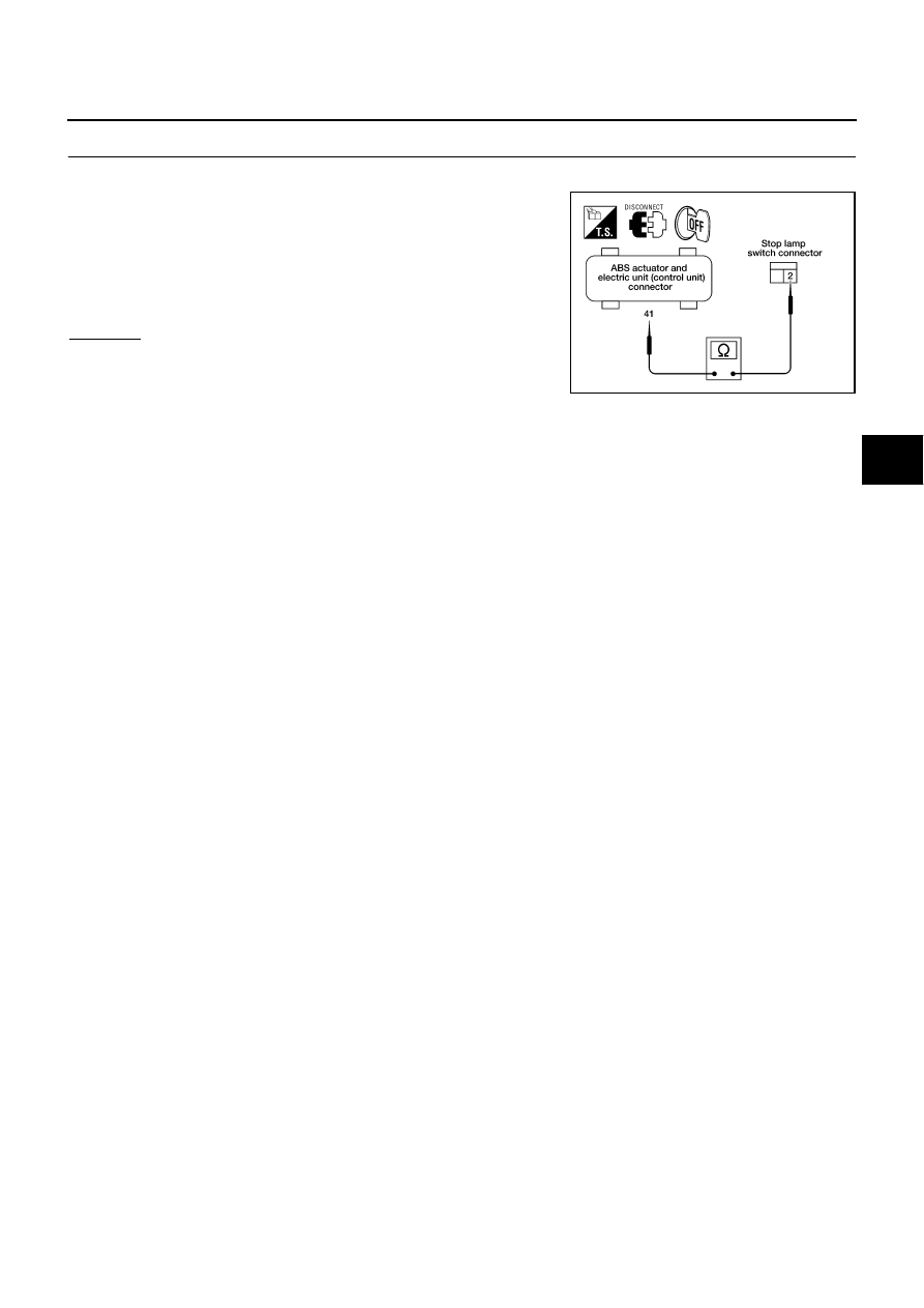
CHECK STOP LAMP SWITCH CIRCUIT

1.

Turn ignition switch “OFF”.

2.

Disconnect stop lamp switch connector E116 and ABS actuator
and electric unit (control unit) connector E24.

3.

Check continuity between stop lamp switch harness connector
E116 and ABS actuator and electric unit (control unit) harness
connector E24. 

OK or NG

OK

>> Connect connectors and perform an ABS actuator and

electric unit (control unit) self-diagnosis.

NG

>> Open or short in harness. Repair or replace harness.

41 - 2

: Continuity should exist.

LFIA0150E

BRC-36

[ABS]

TROUBLE DIAGNOSIS FOR SYMPTOMS

Revision: 2006 July

2007 Murano

TROUBLE DIAGNOSIS FOR SYMPTOMS

PFP:00007

Excessive ABS Function Operation Frequency

NFS000FQ

1. 

CHECK ABS WARNING LAMP DISPLAY

Make sure the ABS warning lamp turns off approximately 2 seconds after the ignition switch is turned on or
when driving.

OK or NG

OK

>> GO TO 2.

NG

>> Perform self-diagnosis. Refer to 

BRC-20, "DESCRIPTION"

 .

2. 

 CHECK BRAKE FORCE DISTRIBUTION

Check front and rear brake force distribution using a brake tester. Refer to 

BR-39, "SERVICE DATA AND

SPECIFICATIONS (SDS)"

 .

OK or NG

OK

>> GO TO 3.

NG

>> Check brake system.

3. 

CHECK FRONT AND REAR AXLE

Make sure there is no excessive play in the front and rear axles. Refer to front axle 

FAX-6, "FRONT WHEEL

HUB AND KNUCKLE"

 , rear axle 

RAX-5, "WHEEL HUB"

 .

OK or NG

OK

>> GO TO 4.

NG

>> Axle inspection and repair.

4. 

 CHECK WHEEL SENSOR AND SENSOR ROTOR

Check the following.

Wheel sensor installation for damage.

Sensor rotor installation for damage. 

Wheel sensor connector connection.

Wheel sensor harness inspection.

OK or NG

OK

>> INSPECTION END.

NG

>> Repair wheel sensor and rotor system.

Unexpected Pedal Reaction

NFS000FR

1. 

CHECK BRAKE PEDAL STROKE

Check brake pedal stroke

BR-7, "Inspection and Adjustment"

 .

Is the stroke too big?

YES

>>

Bleed air from the brake piping. Refer to 

BR-13, "Bleeding Brake System"

 .

Check brake pedal, brake booster, and master cylinder mount for play, looseness, and brake
system for fluid leaks, etc. If any malfunctions are found, make repairs. Brake pedal: 

BR-10,

"Removal and Installation"

 . Brake master cylinder and Brake booster: 

BR-23, "Removal and

Installation"

 .

NO

>> GO TO 2.

TROUBLE DIAGNOSIS FOR SYMPTOMS

BRC-37

[ABS]

C

D

E

G

H

I

J

K

L

M

A

B

BRC

Revision: 2006 July

2007 Murano

2. 

CHECK FUNCTION

1.

Turn ignition switch “OFF”.

2.

Disconnect ABS actuator and electric unit (control unit) connector, and make sure the braking force is suf-
ficient when the ABS is not operating. After the inspection, reconnect connector.

OK or NG

OK

>> GO TO 4. “CHECK WHEEL SENSOR AND SENSOR ROTOR” in  

BRC-36, "Excessive ABS

Function Operation Frequency"

NG

>> Check brake system.

The Braking Distance is Long

NFS000FS

CAUTION:

On slippery road surfaces, the stopping distance might be longer with ABS operating than when ABS
is not operating.

1. 

CHECK FUNCTION

1.

Turn ignition switch “OFF”.

2.

Disconnect VDC/TCS/ABS control unit connector to deactivate ABS. In this condition, check stopping dis-
tance. After inspection, connect connector.

OK or NG

OK

>> GO TO 4. “CHECK WHEEL SENSOR AND SENSOR ROTOR” in  

BRC-36, "Excessive ABS

Function Operation Frequency"

 .

NG

>>

Bleed air from brake piping. 

BR-13, "Bleeding Brake System"

 .

Check brake system.

ABS Function Dose Not Operate

NFS000FT

CAUTION:

ABS does not operate when the speed is 10 km/h (6 MPH) or less.

1. 

CHECK ABS WARNING LAMP DISPLAY

Make sure the ABS warning lamp turns off approximately 2 seconds after the ignition switch is turned on or
when driving.
OK or NG

OK

>> OK or NG

NG

>> Perform self-diagnosis. Refer to 

BRC-20, "DESCRIPTION"

 . 

Pedal Vibration or ABS Operation Sound Occurs

NFS000FU

CAUTION:

Under the following conditions, when brake pedal is lightly depressed (just place a foot on it), ABS is
activated and vibration is felt. However, this is normal.

When shifting gears

When driving on slippery road

During cornering at high speed

When passing over bumps or grooves.

When driving just after starting engine (at approximately 10 km/h (6 MPH) or higher)

1. 

SYMPTOM CHECK 

Check if pedal vibration or operation sound occurs when the engine is started.

OK or NG

OK

>> GO TO 2.

NG

>> Perform self-diagnosis. Refer to 

BRC-20, "DESCRIPTION"

 .

BRC-38

[ABS]

TROUBLE DIAGNOSIS FOR SYMPTOMS

Revision: 2006 July

2007 Murano

2. 

INSPECTION CHECK 1

Does vibration occur during normal parking?

CAUTION:

In addition to activation for sudden braking, ABS may activate in conditions such as those listed 
below.

Roads with low surface.

Turning at high speed.

Passing through gusts of wind.

OK or NG

OK

>> GO TO 3.

NG

>> Normal

3. 

INSPECTION CHECK 2

Check for vibration when engine speed is increased while vehicle is stopped.

OK or NG

OK

>> GO TO 4

NG

>>

Normal

CAUTION:

Vibration may occur when vehicle is stopped.

4. 

INSPECTION CHECK 3

Check for vibration when switches of electrical components are operated.

OK or NG

OK

>> Check for any wireless devices, or antenna lead near control unit (including wiring).

NG

>> GO TO 5.

5. 

CHECK ABS WARNING LAMP INDICATION

Confirm ABS warning lamp turns on.

OK or NG

OK

>> Perform self-diagnosis. Refer to 

BRC-20, "DESCRIPTION"

 .

NG

>> GO TO 4. “CHECK WHEEL SENSOR AND SENSOR ROTOR” in  

BRC-36, "Excessive ABS

Function Operation Frequency"

 .

ABS Warning Lamp Indication is Not Normal

NFS000LM

NOTE:
For lighting condition of ABS warning lamp. refer to 

BRC-27, "ABS WARNING LAMP AND BRAKE WARNING

LAMP"

 .

1. 

CHECK SYSTEM FOR CAN COMMUNICATION LINE

Perform self-diagnosis. Refer to 

BRC-20, "DESCRIPTION"

 .

Is the “CAN COMM CIRCUIT [U1000]” displayed?

YES

>> Perform trouble diagnosis for CAN communication line. Refer to 

BRC-31, "CAN Communication

Circuit"

 .

NO

>> GO TO 2.

TROUBLE DIAGNOSIS FOR SYMPTOMS

BRC-39

[ABS]

C

D

E

G

H

I

J

K

L

M

A

B

BRC

Revision: 2006 July

2007 Murano

2. 

CHECK ABS ACTUATOR AND ELECTRIC UNIT (CONTROL UNIT)

1.

Turn ignition switch “OFF”.

2.

Check ABS actuator electric unit (control unit) input/output signal. Refer to 

BRC-19, "Control Unit Input/

Output Signal Standard"

 .

OK or NG

OK

>> GO TO 3.

NG

>> Check VDC/TCS/ABS control unit pin terminals for damage or loose connection with harness con-

nector. If any item is damaged, repair or replace damaged parts.

3. 

CHECK COMBINATION METER INDICATION

Check the combination meter indication and operation. Refer to 

DI-15, "Self-Diagnosis Mode of Combination

Meter"

 .

OK or NG

OK

>> INSPECTION END.

NG

>> Combination meter is malfunctioning. Check combination meter. Refer to 

DI-4, "COMBINATION

METERS"

 .

BRC-40

[ABS]

WHEEL SENSORS

Revision: 2006 July

2007 Murano

WHEEL SENSORS

PFP:47910

Removal and Installation

NFS000FV

REMOVAL

Be careful of the following.

CAUTION:

As much as possible, avoid rotating wheel sensor when removing it. Pull wheel sensors out with-
out pulling on sensor harness.

Take care to avoid damaging wheel sensor edges or rotor teeth. Remove wheel sensor first before
removing front or rear wheel hub. This is to avoid damage to wheel sensor wiring and loss of sen-
sor function.

INSTALLATION

Be careful of the following. Tighten the mounting bolts and nuts to the specified torque. Refer to 

BRC-40,

"Removal and Installation"

 .

When installing, make sure there is no foreign material such as iron chips on and in the mounting hole of
the wheel sensor. Make sure no foreign material has been caught in the sensor rotor. Remove any foreign
material and clean the mount.

When installing wheel sensor, be sure to press rubber grommets in until they lock at locations shown
above in figure. When installed, harness must not be twisted. 

PFIA0417E

SENSOR ROTOR

BRC-41

[ABS]

C

D

E

G

H

I

J

K

L

M

A

B

BRC

Revision: 2006 July

2007 Murano

SENSOR ROTOR

PFP:47970

Removal and Installation

NFS000FW

REMOVAL
Front

Sensor rotor cannot be disassembled. To replace sensor rotor, replace hub bearing assembly. Refer to 

FAX-6,

"FRONT WHEEL HUB AND KNUCKLE"

  in “FAX” section.

Rear

Sensor rotor cannot be disassembled. To replace sensor rotor, replace hub bearing assembly. Refer to 

RAX-5,

"WHEEL HUB"

  in “RAX” section.

INSTALLATION

Installation is the reverse order of removal.

BRC-42

[ABS]

ACTUATOR AND ELECTRIC UNIT (ASSEMBLY)

Revision: 2006 July

2007 Murano

ACTUATOR AND ELECTRIC UNIT (ASSEMBLY)

PFP:47660

Removal and Installation

NFS000FX

Pay attention to the following when removing actuator.

CAUTION:

Before servicing, disconnect battery cables.

To remove brake tube, use flare nut wrench to prevent flare nuts and brake tube from being dam-
aged. To install, use flare nut torque wrench (commercial service tool).

Do not remove and install actuator by holding harness.

After work is completed, bleed air from brake piping. Refer to 

BR-13, "Bleeding Brake System"

 .

PFIA0800E

1.

To front left

2.

To rear right

3.

To rear left

4.

To front right

5.

From master cylinder secondary 
side

6.

From master cylinder primary side

7.

ABS actuator and electric unit (con-
trol unit)

8.

Harness connector

PRECAUTIONS

BRC-43

[VDC/TCS/ABS]

C

D

E

G

H

I

J

K

L

M

A

B

BRC

Revision: 2006 July

2007 Murano

[VDC/TCS/ABS]

PRECAUTIONS

PFP:00001

Precautions for Supplemental Restraint System (SRS) “AIR BAG” and “SEAT 
BELT PRE-TENSIONER”

NFS000FY

The Supplemental Restraint System such as “AIR BAG” and “SEAT BELT PRE-TENSIONER”, used along
with a front seat belt, helps to reduce the risk or severity of injury to the driver and front passenger for certain
types of collision. This system includes seat belt switch inputs and dual stage front air bag modules. The SRS
system uses the seat belt switches to determine the front air bag deployment, and may only deploy one front
air bag, depending on the severity of a collision and whether the front occupants are belted or unbelted.
Information necessary to service the system safely is included in the SRS and SB section of this Service Man-
ual.

WARNING:

To avoid rendering the SRS inoperative, which could increase the risk of personal injury or death
in the event of a collision which would result in air bag inflation, all maintenance must be per-
formed by an authorized NISSAN/INFINITI dealer.

Improper maintenance, including incorrect removal and installation of the SRS, can lead to per-
sonal injury caused by unintentional activation of the system. For removal of Spiral Cable and Air
Bag Module, see the SRS section.

Do not use electrical test equipment on any circuit related to the SRS unless instructed to in this
Service Manual. SRS wiring harnesses can be identified by yellow and/or orange harnesses or
harness connectors.

Precautions for Brake System

NFS000T8

Recommended fluid is brake fluid “DOT 3”. Refer to

MA-10, "RECOMMENDED FLUIDS AND LUBRI-

CANTS"

 .

Do not reuse drained brake fluid.

Be careful not to splash brake fluid on painted areas.

To clean or wash all parts of master cylinder, disc brake caliper and wheel cylinder, use clean brake fluid.

Do not use mineral oils such as gasoline or kerosene. They will ruin rubber parts of the hydraulic system.

Use a flare nut wrench when removing flare nuts, and use a flare
nut crowfoot and torque wrench when tighten brake tube flare
nuts.

Always torque brake lines when installing.

Before working, turn ignition switch OFF and disconnect electri-
cal connector of ABS actuator and electric control unit (control
unit) or battery negative terminal.

Burnish the brake contact surfaces after refinishing or replacing
drums or rotors, after replacing pads or linings, or if a soft pedal
occurs at very low mileage.
Refer to 

BR-32, "BRAKE BURNISHING PROCEDURE"

 .

WARNING:

Clean brake pads and shoes with a waste cloth, then wipe with a dust collector.

Precautions for Brake Control

NFS000G0

During ABS operation, brake pedal lightly vibrates and a mechanical noise may be heard. This is normal.

Just after starting vehicle after turning ignition switch ON, brake pedal may vibrate or motor operating
noise may be heard from engine compartment. This is a normal status of operation check.

Stopping distance may be longer than that of vehicles without ABS when vehicle drives on rough, gravel,
or snow-covered (fresh, deep snow) roads.

When an error is indicated by ABS or another warning lamp, collect all necessary information from cus-
tomer (what symptoms are present under what conditions) and check for simple causes before starting
diagnostic servicing. Besides electrical system inspection, check brake booster operation, brake fluid
level, and fluid leaks.

If tire size and type are used in an improper combination, or brake pads are not Genuine NISSAN parts,
stopping distance or steering stability may deteriorate.

SBR686C

BRC-44

[VDC/TCS/ABS]

PRECAUTIONS

Revision: 2006 July

2007 Murano

If there is a radio, antenna, or antenna lead-in wire (including wiring) near control module, ABS function
may have a malfunction or error.

If aftermarket parts (car stereo, CD player, etc.) have been installed, check for incidents such as harness
pinches, open circuits, and improper wiring.

If the following components are replaced with non-genuine components or converted, the VDC OFF indi-
cator lamp and SLIP indicator lamp may turn on or the VDC system may not operate properly. Compo-
nents related to suspension (Shock Absorber, Strut, Spring, Bushing, etc.), Tires, wheels (exclude
specified size), components related to brake (Pad, Rotor, Caliper, etc.), Components related to engine
(Muffler, ECM, etc.), Components related to body reinforcement (Roll bar, Tower bar, etc.).

Driving in the condition of breakage or excessive wear of the suspension, tires or components related to
the brakes may cause the VDC OFF indicator lamp and the SLIP indicator lamp to turn on, and the   VDC
system may not operate properly.

When the TCS or VDC is activated by sudden acceleration or sudden turn, some noise may occur. The
noise is a result of the normal operation of the TCS and VDC.

When driving on roads which have extreme slopes (such as mountainous roads) or high banks (such as
sharp carves on a freeway), the VDC may not operate normally, or the VDC warning lamp and the SLIP
indicator lamp may turn on. However, this is not a malfunction if normal operation can be resumed after
restarting the engine.

Sudden turns (such as spin turns, acceleration turns), drifting, etc. When VDC function is OFF (VDC SW
ON) may cause the yaw rate/side G sensor system indicate a malfunction. However, this is not a malfunc-
tion if normal operation can be resumed after restarting the engine.

PREPARATION

BRC-45

[VDC/TCS/ABS]

C

D

E

G

H

I

J

K

L

M

A

B

BRC

Revision: 2006 July

2007 Murano

PREPARATION

PFP:00002

Commercial Service Tools

NFS000G1

Tool name

Description

1.Flare nut crowfoot
a:10 mm (0.39 in)/12 mm (0.47 in)
2.Torque wrench

Installing brake tube

S-NT360

BRC-46

[VDC/TCS/ABS]

ON-VEHICLE SERVICE

Revision: 2006 July

2007 Murano

ON-VEHICLE SERVICE

PFP:00000

Adjustment of Steering Angle Sensor Neutral Position

NFS000G2

After removing/installing or replacing ABS actuator and electric unit (control unit), steering angle sensor, steer-
ing components, suspension components, or after adjusting wheel alignment, make sure to adjust neutral
position of steering angle sensor before running vehicle.

×

: Required

–: Not required

CAUTION:

To adjust neutral position of steering angle sensor, make sure to use CONSULT-II.
(Adjustment can not be done without CONSULT-II.)

1.

Stop vehicle with front wheels in straight-ahead position.

2.

Perform “CONSULT-II Start Procedure”. Refer to 

GI-37, "CONSULT-II Start Procedure"

 .

3.

Touch “WORK SUPPORT”.

4.

Touch “START”on“ST ANGLE SENSOR ADJUSTMENT”screen.

CAUTION:

Do not touch steering wheel while adjusting steering angle
sensor.

5.

After approximately 10 seconds, touch “END”. (After approxi-
mately 60 seconds, it ends automatically.)

6.

Turn ignition switch OFF, then turn it ON again.

CAUTION:

Be sure to perform above operation.

7.

Run vehicle with front wheels in straight-ahead position, then
stop.

8.

Select “DATA MONITOR”, “SELECTION FROM MENU”, and “STR ANGLE SIG” on CONSULT-II screen.
Then make sure “STR ANGLE SIG” is within 0

±

2.5 deg. If value is more than specification, repeat steps 1

to 7.

9.

Erase memory of ABS actuator and electric unit (control unit) and ECM.

10. Turn ignition switch OFF.

Situation

Adjustment of Steering Angle Sensor Neutral Position 

Removing/Installing ABS actuator and electric unit (control unit)

Replacing ABS actuator and electric unit (control unit)

×

Removing/Installing steering angle sensor

×

Removing/Installing steering components

×

Removing/Installing suspension components

×

Change tires to new ones

Tire rotation

Adjustment wheel alignment

×

SFIA0371E

ON-VEHICLE SERVICE

BRC-47

[VDC/TCS/ABS]

C

D

E

G

H

I

J

K

L

M

A

B

BRC

Revision: 2006 July

2007 Murano

Calibration of Decel G Sensor

NFS000G3

After removing/installing or replacing yaw rate/side/decel G sensor, ABS actuator and electric unit (control
unit) make sure to Calibration of Decel G Sensor before running vehicle.

×

: Required

–: Not required

CAUTION:

To adjust neutral position of steering angle sensor, make sure to use CONSULT-II.
(Adjustment can not be done without CONSULT-II.)

1.

Stop vehicle with front wheels in straight-ahead position.

CAUTION:

Keep all tires inflated to correct pressures. Adjust the tire pressure to the specified pressure
value.

See that there is on-load in vehicle other than the driver (or equivalent weight placed in driver's
position).

2.

Perform “CONSULT-II Start Procedure”. Refer to 

GI-37, "CONSULT-II Start Procedure"

 .

3.

Touch “WORK SUPPORT”.

4.

Touch “START” on “DECEL G SEN CALIBRATION” on CON-
SULT- II screen.

5.

After approximately 10 seconds, touch “END”. (After approxi-
mately 60 seconds, it ends automatically.)

6.

Turn ignition switch OFF, then turn it ON again.

CAUTION:

Be sure to carry out above operation.

7.

Run vehicle with front wheels in straight-ahead position, then
stop.

8.

Select “DATA MONITOR”, “SELECTION FROM MENU”, and
“DECEL G SEN” on CONSULT- II screen. Then check that
“DECEL G SEN” is within 

±

0.08 G. If value is more than specification, repeat steps 1 to 5.

9.

Erase memory of ABS actuator and electric unit (control unit) and ECM.

10. Turn ignition switch OFF.

Situation

Calibration of Decel G Sensor

Removing/Installing ABS actuator and electric unit (control unit)

×

Removing/Installing steering components

Removing/Installing suspension components

Change tires to new ones

Tire rotation

Adjusting wheel alignment

Removing/Installing Yaw rate/side/decel G sensor

×

LFIA0171E

BRC-48

[VDC/TCS/ABS]

SYSTEM DESCRIPTION

Revision: 2006 July

2007 Murano

SYSTEM DESCRIPTION

PFP:00000

System Diagram

NFS000G4

COMPONENTS FUNCTION DESCRIPTION

PFIA0740E

Components

Description

ABS actuator and electric unit 
(control unit)

Receives the information of various sensor signals, engine and AT, and then determines the 
vehicle driving status. Performs the calculations of target brake fluid pressure, of brake actuator 
drive signal output and of engine torque required for the VDC/TCS/ABS control.

Receives the actuator drive signal from ABS actuator and electric unit (control unit), and then 
performs the brake fluid adjustment of each wheel caliper.

Yaw rate side/decel G sensor

Detects the yaw rate and side G of the vehicle.

Steering angle sensor

Detects the operating angle and direction of driver steering wheel.

Wheel sensor

Detects the rotation speed of each wheel.

VDC OFF switch

Cancels the VDC function.

ECM

Receives the command from ABS actuator and electric unit (control unit), and then performs the 
controls of throttle motor and injector.

SYSTEM DESCRIPTION

BRC-49

[VDC/TCS/ABS]

C

D

E

G

H

I

J

K

L

M

A

B

BRC

Revision: 2006 July

2007 Murano

Function

NFS000G6

VDC

In addition to the TCS/ABS function, the driver steering amount and brake operation amount are detected
from the steering angle sensor and pressure sensor, and the vehicle's driving status (amount of under
steering / over steering) is determined from information from the yaw rate side/decel G sensor, wheel sen-
sor, etc., and this information is used to improve vehicle stability by controlling the braking and engine
power to all four wheels.

The SLIP indicator lamp flashes to inform the driver of VDC operation.

During VDC operation, the body and brake pedal lightly vibrate and mechanical noises may be heard.
This is normal.

The ABS warning lamp, VDC OFF indicator lamp, and SLIP indicator lamp might turn on when the vehicle
is subject to strong shaking or large vibration, such as when the vehicle is on a turn table or a ship while
the engine is running or steep slope such as bank. In this case, restart the engine on a normal road, and if
the ABS warning lamp, VDC OFF indicator lamp, and SLIP indicator lamp turn off, there is no malfunction.

TCS

The wheel spin of the drive wheels is detected by the ABS actuator and electric unit (control unit) from the
wheel speed signals from the four wheels, so if wheel spin occurs, the drive wheel right and left brake fluid
pressure control and engine fuel cut are conducted while the throttle value is restricted to reduce the
engine torque and decrease the amount of wheel spin. In addition, the degree the throttle is opened is
controlled to achieve the optimum engine torque.

Depending on road circumstances, the driver may have a sluggish feel. This is normal, because the opti-
mum traction has the highest priority under TCS operation.

TCS may be activated any time the vehicle suddenly accelerates, depressing accelerator peal fully, sud-
denly downshifts, upshifts, or is driven on a road with a varying surface friction coefficient.

During TCS operation, it informs a driver of system operation by flashing SLIP indicator lamp.

ABS

The Anti-Lock Braking System is a function that detects wheel revolution while braking, and it improves
handling stability during sudden braking by electrically preventing 4 wheel lock. Maneuverability is also
improved for avoiding obstacles.

 If the electrical system malfunction, then Fail-Safe function is activated, ABS becomes inoperative, and
ABS warning lamp turns on.

Electrical system diagnosis by CONSULT-II is available.

During ABS operation, brake pedal lightly vibrates and a mechanical noise may be heard. This is normal.

Just after starting vehicle after ignition switch ON, brake pedal may vibrate or motor operating noise may
be heard from engine compartment. This is a normal status of operation check.

Stopping distance may be longer than that of vehicles without ABS when vehicle drives on rough, gravel,
or snow-covered (fresh, deep snow) roads.

EBD

Electronic Brake Distribution is a function that detects subtle slippages between front and rear wheels dur-
ing braking, and it improves handling stability by electronically controlling Brake Fluid Pressure which
results in reduced rear wheel slippage.

In case of electrical system malfunction, Fail-Safe function is activated, EBD and ABS becomes inopera-
tive, and ABS warning lamp and brake warning lamp are turned on.

Electrical system diagnosis by CONSULT-II is available.

During EBD operation, brake pedal lightly vibrates and a mechanical noise may be heard. This is normal.

Just after starting vehicle after ignition switch ON, brake pedal may vibrate or motor operating noise may
be heard from engine compartment. This is a normal status of operation check.

Stopping distance may be longer than that of vehicles without EBD when vehicle drives on rough, gravel,
or snow-covered (fresh, deep snow) roads.

BRC-50

[VDC/TCS/ABS]

SYSTEM DESCRIPTION

Revision: 2006 July

2007 Murano

Hydraulic Circuit Diagram

NFS000GB

HYDRAULIC COMPONENTS FUNCTION DESCRIPTION

CAN Communication

NFS000GC

SYSTEM DESCRIPTION

CAN (Controller Area Network) is a serial communication line for real time application. It is an on-vehicle mul-
tiplex communication line with high data communication speed and excellent error detection ability. Many elec-
tronic control units are equipped onto a vehicle, and each control unit shares information and links with other
control units during operation (not independent). In CAN communication, control units are connected with 2
communication lines (CAN H line, CAN L line) allowing a high rate of information transmission with less wiring.
Each control unit transmits/receives data but selectively reads required data only. Refer to 

LAN-49, "CAN Sys-

tem Specification Chart"

 . 

PFIA0452E

Components

Description

Solenoid valve
(ABS control valve)

Increases, maintains and decreases the fluid pressure of each caliper according to the signal from 
VDC/TCS/ABS control unit.

Reservoir

When decreasing the caliper pressure, temporarily saves the brake fluid drained form the caliper in 
order to perform the work efficiently.

Pump

Refills the brake fluid saved in the reservoir via the damper to the caliper.

Motor

Operates the pump according to the signal from VDC/TCS/ABS control unit.

Inlet valve

Leaves the brake fluid drained from the reservoir to the pump so as not to return it to the reservoir.

Outlet valve

Leaves the brake fluid drained from the pump so as not to return it to the pump.

Return check valve

When releasing the brake, bypasses with the orifice of solenoid valve, and then refills the brakefluid 
of caliper to the master cylinder.

Damper

Controls the pulsation of brake fluid drained from the pump, and then weakens the pedal vibration 
during VDC/TCS/ABS operation.

VDC switch-over valve (CV)

Shuts out the normal brake passage from master cylinder during VDC/TCS operation.

VDC switch-over valve (SV)

Supplies the brake fluid from master cylinder to the pump during VDC/TCS operation.


Content      ..     38      39      40      41     ..