Nissan Murano Z50 (2007 year). Manual - part 27
REAR DOOR LOCK
BL-177
C
D
E
F
G
H
J
K
L
M
A
B
BL
Revision: 2006 July
2007 Murano
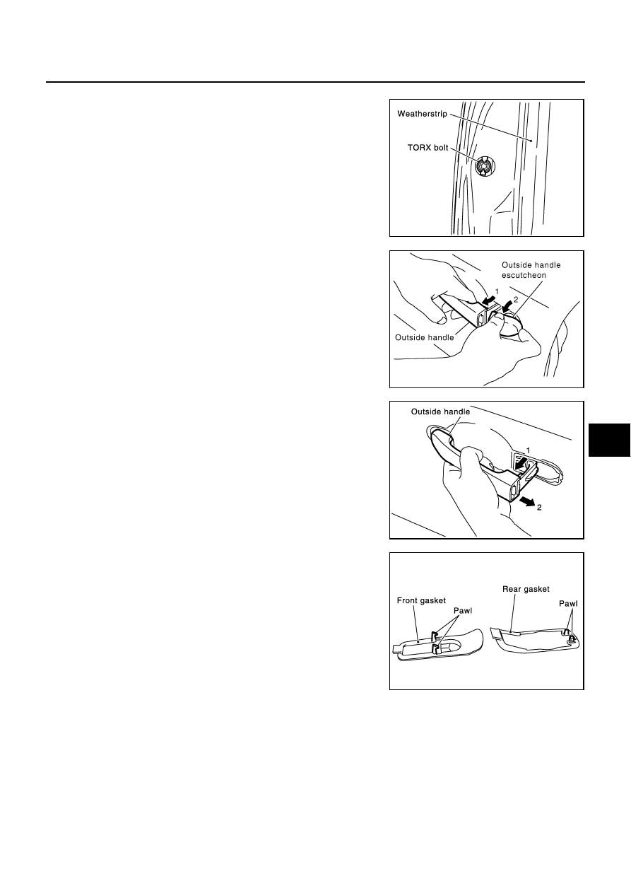
CAUTION:
Do not forcibly remove the TORX bolts (T30).
6.
While pulling the outside handle, remove outside handle
escutcheon.
7.
While pulling outside handle, slide toward rear of vehicle to
remove outside handle.
8.
Remove the front gasket and rear gasket.
PIIA3553E
PIIA6344E
PIIA3555E
PIIA3557E