Nissan Murano Z50 (2007 year). Manual - part 26
INTELLIGENT KEY SYSTEM
BL-161
C
D
E
F
G
H
J
K
L
M
A
B
BL
Revision: 2006 July
2007 Murano
Check Select Unlock Relay
NIS00186
1.
CHECK PASSENGER SIDE SELECT UNLOCK RELAY INPUT SIGNAL
1.
Turn ignition switch OFF.
2.
Check voltage between Intelligent Key unit harness connector and ground.
OK or NG
OK
>> Passenger side select unlock relay circuit is OK.
NG
>> GO TO 2.
2.
CHECK PASSENGER SIDE SELECT UNLOCK RELAY POWER SUPPLY CIRCUIT
1.
Disconnect passenger side select unlock relay.
2.
Check voltage between passenger side select unlock harness connector M123 terminal 2 and ground.
OK or NG
OK
>> GO TO 3.
NG
>> Repair or replace passenger side select unlock relay
power circuit.
3.
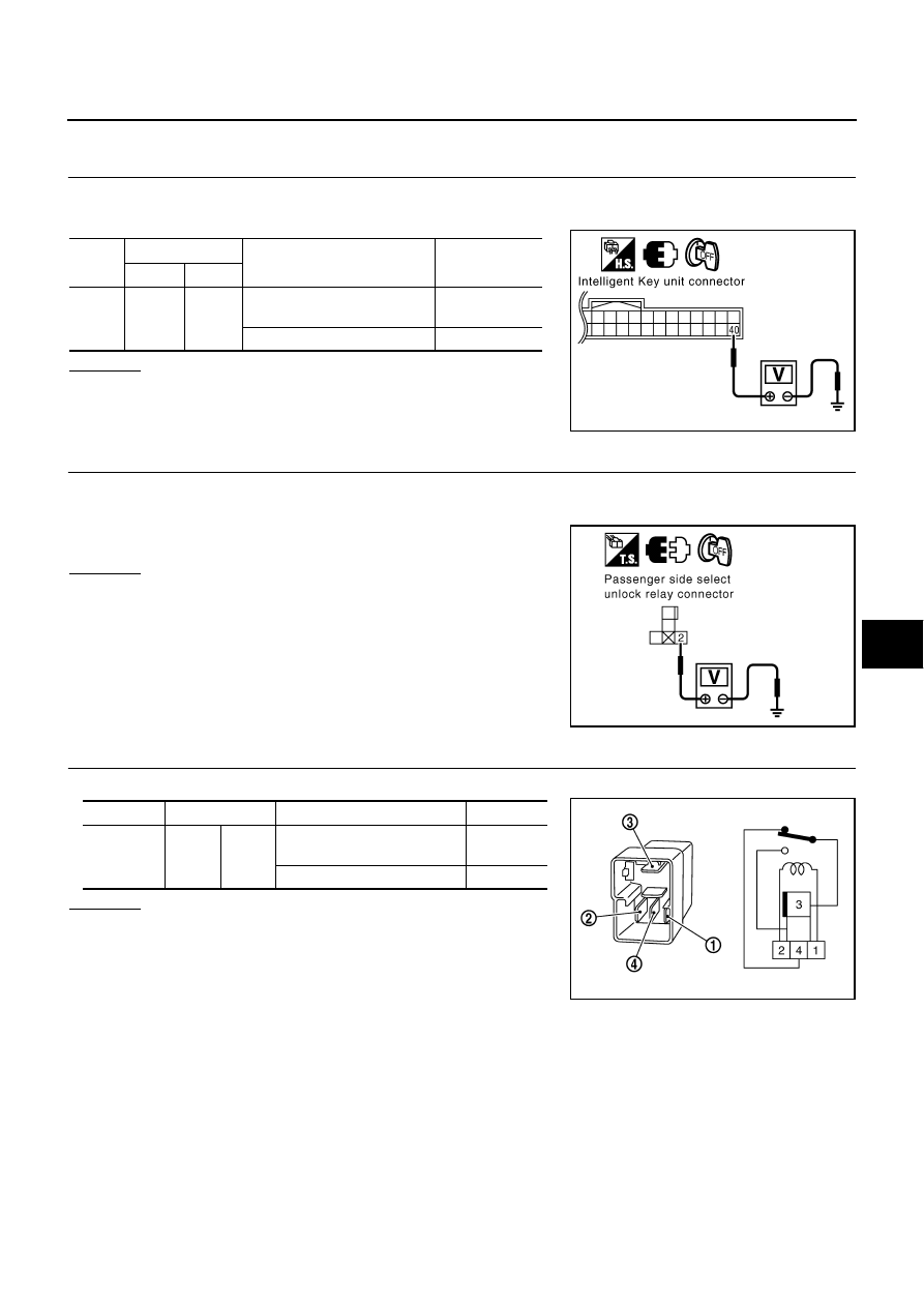
CHECK PASSENGER SIDE SELECT UNLOCK RELAY
Check continuity between passenger side select unlock relay terminals 3 and 4.
OK or NG
OK
>> GO TO 4
NG
>> Replace passenger side select unlock relay.
Con-
nector
Terminals
Condition
Voltage (V)
(Approx.)
(+)
(-)
M99
40 (L/R)
Ground
Press door request switch
(passenger side) once
0
Other than above
Battery voltage
PIIB4352E
2 (Y/R) – Ground
: Battery voltage.
PIIB4353E
Connector
Terminals
Condition
Continuity
M123
3
4
12V direct current supply
between terminals 1 and 2
Yes
Other than above
No
PIIB4355E