Nissan Murano Z50 (2007 year). Manual - part 13


  Index      Manuals     Nissan Murano Z50 (2007 year) - Service and Repair Manual


Search            copyright infringement  


Content      ..     11      12      13      14     ..


Nissan Murano Z50 (2007 year). Manual - part 13


NAVIGATION SYSTEM

AV-169

C

D

E

F

G

H

I

J

L

M

A

B

AV

Revision: 2006 July

2007 Murano

Diagnosis by Error History

When having a difficulty on the investigation of cause due to multiple errors with a reproducible malfunc-
tion, turn ON the ignition switch from OFF mode after making a memo of the item and number of time (or
delete “Error History”). Check “Error History” again after the malfunction was reproduced, and then per-
form diagnosis focusing on the item of which number of time increased.

DVD-ROM error history may be restored because DVD-ROM cannot be temporarily read. (Driving on
rough road etc.) Then, erase the error history. (This is not a malfunction.) Perform service in “Action to
take” if error history are repeatedly indicated again.
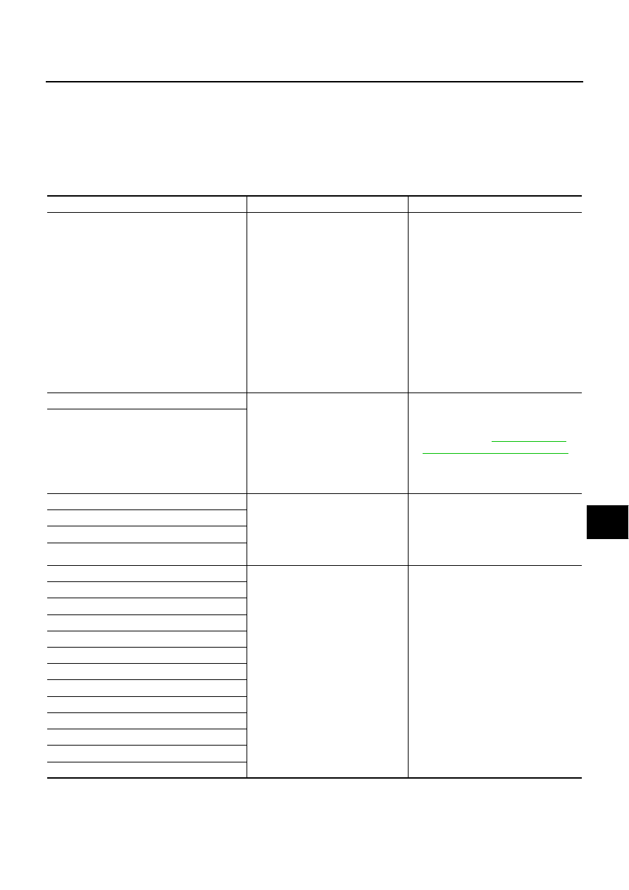
Error item

Possible cause

Action to take

GPS Antenna Error

GPS antenna connection malfunction 
is detected.

1. Start self-diagnosis, and make sure of 

the result.

2. If any error is found, GO TO 3. If any 

error is not found, delete the error his-
tory and end the diagnosis. (This is not 
a malfunction.)

3. Check if GPS antenna feeder line is 

snapped or pinched.

4. If the results from the above checkup 

show no malfunction, replace GPS 
antenna, and then restart self-diagno-
sis.

5. If self-diagnosis results still show any 

malfunction, replace NAVI control unit.

FLASH-ROM Error Of Control Unit

NAVI control unit malfunction is 
detected.

1. Start self-diagnosis, and make sure of 

the result.

2. If any error is found, replace NAVI con-

trol unit. Refer to 

AV-198, "Removal 

and Installation of NAVI Control Unit"

 . 

If any error is not found, delete the error 
history and end the diagnosis. (This is 
not a malfunction.)

Connection Of Gyro

GPS Communication Error

GPS malfunction is detected.

If the symptoms such as the GPS receipt 
malfunction occur, intermittent malfunc-
tion caused by strong radio interference 
may be detected.
If the malfunction always occurs, replace 
NAVI control unit.

GPS ROM Error

GPS RAM Error

GPS RTC Error

DVD-ROM Mechanism not Detected

Malfunction is detected on DVD-
ROM drive pickup lens in NAVI con-
trol unit.

There is dirt and damage on the 
DVD-ROM.

1. Check if the inserted DVD-ROM is 

specified for this navigation system, 
and the DVD-ROM is dirty, scratched or 
warped.

2. If the results from the above checkup 

show no malfunction, insert the same 
DVD-ROM, and then restart self-diag-
nosis.

3. If self-diagnosis results still show any 

malfunction, replace NAVI control unit.

DVD-ROM Communication Error

DVD-ROM Mechanism Error

DVD-ROM Focus Error

DVD-ROM TOC Error

DVD-ROM Disc Error

DVD-ROM Seek Error

DVD-ROM Error Correction Error

DVD-ROM Read Error

DVD-ROM Data Transfer Error

DVD-ROM Data Error

DVD-ROM Loading / Eject Error

DVD-ROM Time-out

AV-170

NAVIGATION SYSTEM

Revision: 2006 July

2007 Murano

Delete Unit Connection Log

Erase the connection history of unit and error history that is recorded
in NAVI control unit (clear the connection history of the removed
unit).

SKIB6979E

NAVIGATION SYSTEM

AV-171

C

D

E

F

G

H

I

J

L

M

A

B

AV

Revision: 2006 July

2007 Murano

CAN DIAG SUPPORT MONITOR

NKS0023S

OPERATION PROCEDURE 

1.

Start the engine.

2.

Turn the audio system OFF.

3.

While pressing the “4” button, turn the volume control dial clock-
wise or counterclockwise for 30 clicks or more. (When the self-
diagnosis mode is started, a short beep will be heard.)

Shifting from current screen to previous screen is performed
by pressing “BACK” button.

4.

The initial trouble diagnosis screen will be shown, and items
“Self Diagnosis (DCU)”, “Self Diagnosis (NAVI)”, “Confirmation/
Adjustment” and “CAN DIAG SUPPORT MONITOR” will
become selective.

5.

Select “CAN DIAG SUPPORT MONITOR”.

6.

The transmitting/receiving of CAN communication can be moni-
tored.

NOTE:
Counter shows the status of CAN communication.

SKIB7750E

SKIB7874E

Item

Content

Error counter

(Reference value)

CAN_COMM

OK/NG

0 - 50

CAN_CIRC_1

OK/UNKWN

0 - 50

CAN_CIRC_2

OK/UNKWN

0 - 50

CAN_CIRC_3

OK/UNKWN

0 - 50

CAN_CIRC_4

OK/UNKWN

0 - 50

CAN_CIRC_5

OK/UNKWN

0 - 50

CAN_CIRC_6

OK/UNKWN

0 - 50

CAN_CIRC_7

OK/UNKWN

0 - 50

CAN_CIRC_8

OK/UNKWN

0 - 50

CAN_CIRC_9

OK/UNKWN

0 - 50

SKIA4288E

AV-172

NAVIGATION SYSTEM

Revision: 2006 July

2007 Murano

A/C and AV Switch Self-Diagnosis Function

NKS002Q2

Performing self-diagnosis makes it possible to check operation of A/C and AV switch indicator (LED) and other
switch.

STARTING THE SELF-DIAGNOSIS MODE

1.

Turn ignition switch from OFF to ACC.

2.

Within 10 seconds press and hold the switches “1” and “6”
simultaneously for 3 seconds.

DIAGNOSIS FUNCTION 

The following are checked:

All the indicators (LED) in the A/C and AV switch.

Continuity of the switches by sounding the buzzer when the A/C and AV switch and audio steering switch
is pressed.

Continuity of harness between A/C and AV switch and audio steering switch.

NOTE:
Impossible to check rear window defogger switch operation (No beep sound even under normal status).

EXITING THE SELF-DIAGNOSIS MODE

Turn ignition switch OFF.

SKIB7704E

NAVIGATION SYSTEM

AV-173

C

D

E

F

G

H

I

J

L

M

A

B

AV

Revision: 2006 July

2007 Murano

CONSULT-II Functions (REAR VIEW CAMERA)

NKS0023U

CONSULT-II can display each diagnostic item using the diagnostic test modes shown following.

CONSULT-II BASIC OPERATION PROCEDURE

Refer to 

GI-37, "CONSULT-II Start Procedure"

 .

WORK SUPPORT
Operation Procedure

1.

Touch “WORK SUPPORT” on “SELECT DIAG MODE” screen.

2.

Touch “SELECT GUIDELINE PATTERN” or “ADJ GUIDELINE POSITION” on “SELECT WORK ITEM”
screen.

For details, refer to 

AV-174, "Vehicle Width and Distance Guiding Line Correction"

 .

DATA MONITOR
Operation Procedure

1.

Touch “DATA MONITOR” on “SELECT DIAG MODE” screen.

2.

Touch either “ALL SIGNALS” or “SELECTION FROM MENU” on “SELECT MONITOR ITEM” screen.

3.

When “SELECTION FROM MENU” is selected, touch individual items to be monitored. When “ALL SIG-
NALS” is selected, all the items will be monitored.

4.

Touch “START”.

5.

Touch “RECORD” while monitoring, then the status of the monitored item can be recorded. To stop
recording, touch “STOP”.

Display Item List

Diagnosis part

Check Item, 

Diagnosis Mode

Description

REAR VIEW CAMERA

WORK SUPPORT

It can adjust the vehicle width and distance guiding lines that overlap camera image.

DATA MONITOR

Displays input data for rear view camera control unit in real-time.

ECU PART NUMBER

Displays rear view camera control unit part number.

Item

Description

SELECT GUIDELINE PATTERN

The opening of the vehicle width and distance guiding lines can be selected from 2 patterns.

ADJ GUIDELINE POSITION

Make fine adjustment to the vehicle width and distance guiding lines upper/lower/left/right

Item

Description

ALL SIGNALS

Monitors all the signal.

SELECTION FROM MENU

Selects and monitors individual items.

Item

Description

R POSI SIG [ON/OFF]

“ON (Selector lever R position)/OFF (other than R position)” status as judged from the reverse 
signal is displayed.

AV-174

NAVIGATION SYSTEM

Revision: 2006 July

2007 Murano

Vehicle Width and Distance Guiding Line Correction

NKS0023V

DESCRIPTION

CONSULT-II is used to modify the guiding lines of the width of vehicle and the distance from rear end of vehi-
cle on the rear view monitor when these lines are derated from the actual width and/or distance, because of
rear view camera replacement, etc.

VEHICLE WIDTH AND DISTANCE GUIDING LINE CORRECTION PROCEDURE

1.

Create a correction line to modify the guiding lines inside moni-
tors. Draw lines on the rearward area of the vehicle passing
through the following points: 200 mm (7.87 in) from both sides of
the vehicle, and 0.5 m (1.64 ft), 1 m (3.28 ft), 2 m (6.56 ft), and 3
m (9.84 ft) from the rear end of the bumper.

2.

Connect CONSULT-II and CONSULT-II CONVERTER, and then
touch “REARVIEW CAMERA” on “SELECT SYSTEM” screen.

WARNING:

Correct the guiding line with the engine stopped for safety.

3.

Shift selector lever to R position.

SKIB7827E

BCIA0030E

SKIB3094E

NAVIGATION SYSTEM

AV-175

C

D

E

F

G

H

I

J

L

M

A

B

AV

Revision: 2006 July

2007 Murano

4.

Touch “ADJ GUIDELINE POSITION” on “SELECT WORK
ITEM” screen.

NOTE:
When starting “ADJ GUIDELINE POSITION” mode, vehicle
width guiding lines may move horizontally. It is normal.

5.

Touch “X UP”, “X DOWN”, “Y UP”, and “Y DOWN” so as to align
with a correction line created, and then adjust the guiding lines.

6.

If the guiding lines align with the correction lines, touch “SAVE”
so as to fix the lines, and then end the correction by touching
“END”. GO TO 7 if the guiding lines do not align with the correc-
tion lines.

7.

Touch “SELECT GUIDELINE PATTERN” on SELECT WORK
ITEM screen.

8.

Change the pattern of the guiding lines by touching “UP” or
“DOWN”. [Select from among 2 patterns (“PATTERN NO. 0 or
1”) of the guiding lines.]

9.

Fix the pattern of the guiding lines by touching “SAVE”.

10. End the correction by touching “END”.

NOTE:
If the setting value is changed on “SELECT GUIDELINE PAT-
TERN” and “ADJ GUIDELINE POSITION”, the change is not
reflected at the next starting if “SAVE” is not touched.

SKIA5638E

Adjustment direction

ADJUST MONITOR

LEFT/RIGHT

X VALUE ADJ

–8 - 8

UP/DOWN

Y VALUE ADJ

–8 - 8

SKIB0841E

SKIA5638E

SKIB0842E

AV-176

NAVIGATION SYSTEM

Revision: 2006 July

2007 Murano

CAN Communication Check

NKS0024D

1. 

CHECK MONITOR DESCRIPTION

1.

Start self-diagnosis of DCU. Refer to 

AV-158, "Self-Diagnosis Mode (DCU)"

 .

2.

Select “CAN DIAG SUPPORT MONITOR”. Refer to 

AV-171,

"CAN DIAG SUPPORT MONITOR"

 .

3.

Record each item display description (OK/NG/UNKWN) displayed on the following CAN DIAG SUPPORT
MONITOR Check Sheet.

CAN DIAG SUPPORT MONITOR Check Sheet

>> After filling in CAN DIAG SUPPORT MONITOR Check Sheet, GO TO 

LAN-3, "Precautions When

Using CONSULT-II"

 .

Item

 content

Error counter

(Reference value)

Normal condition

Error (Example)

CAN_COMM

OK

NG

0 - 50

CAN_CIRC_1

OK

UNKWN

0 - 50

CAN_CIRC_2

OK

UNKWN

0 - 50

CAN_CIRC_3

OK

UNKWN

0 - 50

CAN_CIRC_4

OK

UNKWN

0 - 50

CAN_CIRC_5

OK

UNKWN

0 - 50

CAN_CIRC_6

OK

UNKWN

0 - 50

CAN_CIRC_7

OK

UNKWN

0 - 50

CAN_CIRC_8

OK

UNKWN

0 - 50

CAN_CIRC_9

UNKWN

UNKWN

0 - 50

PKIB6080E

Diagnosis item

Screen display

Diagnosis item

Screen display

CAN_COMM

OK

NG

CAN_CIRC_5

OK

UNKWN

CAN_CIRC_1

OK

UNKWN

CAN_CIRC_6

OK

UNKWN

CAN_CIRC_2

OK

UNKWN

CAN_CIRC_7

OK

UNKWN

CAN_CIRC_3

OK

UNKWN

CAN_CIRC_8

OK

UNKWN

CAN_CIRC_4

OK

UNKWN

CAN_CIRC_9

OK

UNKWN

NAVIGATION SYSTEM

AV-177

C

D

E

F

G

H

I

J

L

M

A

B

AV

Revision: 2006 July

2007 Murano

Unable to Operate System with A/C and AV Switch

NKS0024U

Symptom: Unable to operate A/C system, audio system and navigation system with A/C and AV switch.
(Unable to start self-diagnosis.)

1. 

CHECK CONDITION

1.

Turn ignition switch ON.

2.

Check if an image is displayed on the screen.

Is an image displayed on the screen?

YES

>> GO TO 2.

NO

>> Repair malfunctioning part. Refer to 

AV-179, "All Images Are Not Displayed"

 .

2. 

SELF-DIAGNOSIS OF A/C AND AV SWITCH

Start self-diagnosis of A/C and AV switch, and check the self-diagnosis result. Refer to 

AV-172, "A/C and AV

Switch Self-Diagnosis Function"

 .

OK or NG

OK

>> GO TO 4.

NG

>> GO TO 3.

3. 

CHECK A/C AND AV SWITCH POWER SUPPLY AND GROUND CIRCUIT

1.

Check voltage between A/C and AV switch harness connector
terminals and ground.

2.

Turn ignition switch OFF. 

3.

Disconnect A/C and AV switch connector.

4.

Check continuity between A/C and AV switch harness connector
M48 terminal 5 and ground.

OK or NG

OK

>> Replace A/C and AV switch.

NG

>> Repair harness or connector.

Terminals

OFF

ACC

ON

(+)

(–)

Connector

Terminal 

M48

1

Ground

Battery 
voltage

Battery 
voltage

Battery 
voltage

2

0  V

Battery 
voltage

Battery 
voltage

5 – Ground

: Continuity should exist.

SKIB7836E

SKIB7837E

AV-178

NAVIGATION SYSTEM

Revision: 2006 July

2007 Murano

4. 

CHECK HARNESS

1.

Turn ignition switch OFF.

2.

Disconnect display control unit and A/C and AV switch connectors.

3.

Check continuity between display control unit harness connector
(A) M43 terminals 28, 30 and A/C and AV switch harness con-
nector (B) M48 terminals 6, 8.

4.

Check continuity between display control unit harness connector
(A) M43 terminals 28, 30 and ground.

OK or NG

OK

>> GO TO 5.

NG

>> Repair harness or connector.

5. 

CHECK A/C AND AV SWITCH AND DISPLAY CONTROL UNIT

1.

Replace A/C and AV switch or display control unit.

2.

Make sure that A/C system, audio system and navigation system can be operated by A/C and AV switch.

OK or NG

OK

>> INSPECTION END

NG

>> Replace the other unit.

28 – 6

: Continuity should exist.

30 – 8

: Continuity should exist.

28, 30 – Ground

: Continuity should not exist.

SKIB7838E

NAVIGATION SYSTEM

AV-179

C

D

E

F

G

H

I

J

L

M

A

B

AV

Revision: 2006 July

2007 Murano

All Images Are Not Displayed

NKS0024L

Symptom: RGB image and rear view image are not displayed.

1. 

CHECK CONDITION

When operating audio and air conditioner, make sure that they operate correctly.

Do audio and air conditioner operate normally?

YES

>> GO TO 2.

NO

>> GO TO 5.

2. 

CHECK DISPLAY GROUND CIRCUIT

1.

Turn ignition switch OFF.

2.

Disconnect display connector.

3.

Check continuity between display harness connector M38 termi-
nal 1 and ground.

OK or NG

OK

>> GO TO 3.

NG

>> Repair harness or connector.

3. 

CHECK HARNESS

1.

Disconnect display control unit connector.

2.

Check continuity between display control unit harness connector
(A) M42 terminals 2, 4, 5, 7 and display harness connector (B)
M38 terminals 2, 3, 13, 14.

3.

Check continuity between display control unit harness connector
(A) M42 terminals 2, 4 and ground.

OK or NG

OK

>> GO TO 4.

NG

>> Repair harness or connector.

1 – Ground

: Continuity should exist.

SKIB7839E

2 – 2

: Continuity should exist.

4 – 3

: Continuity should exist.

5 – 13

: Continuity should exist.

7 – 14

: Continuity should exist.

2, 4 – Ground

: Continuity should not exist.

SKIB7840E

AV-180

NAVIGATION SYSTEM

Revision: 2006 July

2007 Murano

4. 

 CHECK DISPLAY POWER SUPPLY AND GROUND CIRCUIT (INVERTER AND SIGNAL)

1.

Connect display control unit and display connectors.

2.

Turn ignition switch ON.

3.

Check voltage between display control unit harness connector
M42 terminals 2 and 5.

4.

Check voltage between display control unit harness connector
M42 terminals 4 and 7.

OK or NG

OK

>> Replace display.

NG

>> Replace display control unit.

5. 

CHECK DISPLAY CONTROL UNIT POWER SUPPLY AND GROUND CIRCUIT

1.

Check voltage between display control unit harness connector
terminals and ground.

2.

Turn ignition switch OFF.

3.

Disconnect display control unit connector.

4.

Check continuity between display control unit harness connector
M42 terminal 3 and ground.

OK or NG

OK

>> Replace display control unit.

NG

>> Repair harness or connector.

2 – 5

: Approx. 9 V

SKIB7841E

4 – 7

: Approx. 9 V

SKIB7842E

Terminals

OFF

ACC

ON

(+)

(–)

Connector

Terminal

M42

1

Ground

Battery 
voltage

Battery 
voltage

Battery 
voltage

10

0 V

Battery 
voltage

Battery 
voltage

3 – Ground

: Continuity should exist.

SKIB7843E

SKIB7844E

NAVIGATION SYSTEM

AV-181

C

D

E

F

G

H

I

J

L

M

A

B

AV

Revision: 2006 July

2007 Murano

Rear View Image Is Not Displayed (RGB Image Is Displayed)

NKS0024T

Symptom: Rear view image is not displayed when selector lever is set in R position. (RGB image is displayed.)

1. 

CHECK CONDITION

1.

Turn ignition switch ON.

2.

Check if the screen holds current display or shows nothing but warning message when shifting selector
lever to R position.

Does the screen change?

YES

>> GO TO 2.

NO

>> GO TO 12.

2. 

CONSULT-II FUNCTIONS

1.

With the ignition switch OFF, connect “CONSULT-II” and “CONSULT-II CONVERTER” to the data link con-
nector, and then turn the ignition switch ON. Refer to 

AV-173, "CONSULT-II BASIC OPERATION PROCE-

DURE"

 .

2.

Check if “REARVIEW CAMERA” is shown on the SELECT SYSTEM screen.

Is “REARVIEW CAMERA” shown?

YES

>> GO TO 3.

NO

>> Check rear view camera control unit power supply and ground circuit, and repair malfunctioning

part.

3. 

CONSULT-II FUNCTIONS

Check if reverse signals input to the rear view camera control unit are normal with DATA MONITOR. Refer to

AV-173, "DATA MONITOR"

 .

OK or NG

OK

>> GO TO 4.

NG

>> Check rear view camera control unit reverse signal circuit, and repair malfunctioning part.

4. 

CHECK HARNESS

1.

Turn ignition switch OFF.

2.

Disconnect rear view camera control unit and rear view camera connectors.

3.

Check continuity between rear view camera control unit harness
connector (A) B37 terminals 8, 10 and rear view camera har-
ness connector (B) D109 terminals 1, 3.

4.

Check continuity between rear view camera control unit harness
connector (A) B37 terminals 8, 10 and ground.

OK or NG

OK

>> GO TO 5.

NG

>> Repair harness or connector.

8 – 1

: Continuity should exist.

10 – 3

: Continuity should exist.

8, 10 – Ground

: Continuity should not exist.

SKIB6985E

AV-182

NAVIGATION SYSTEM

Revision: 2006 July

2007 Murano

5. 

CHECK REAR VIEW CAMERA GROUND CIRCUIT

Check continuity between rear view camera harness connector
D109 terminal 2 and ground.

OK or NG

OK

>> GO TO 6.

NG

>> Repair harness or connector.

6. 

CHECK REAR VIEW CAMERA POWER SUPPLY CIRCUIT

1.

Connect rear view camera control unit and rear view camera connectors.

2.

Turn ignition switch ON.

3.

When displaying rear view image, check voltage between rear
view camera control unit harness connector B37 terminal 8 and
ground.

OK or NG

OK

>> GO TO 7.

NG

>> Replace rear view camera control unit.

7. 

CHECK REAR VIEW IMAGE SIGNAL

When displaying rear view image, check voltage waveform between
rear view camera control unit harness connector B37 terminal 10
and ground with CONSULT-ll or oscilloscope.

OK or NG

OK

>> GO TO 8.

NG

>> Replace rear view camera.

2 – Ground

: Continuity should exist.

SKIB6986E

8 – Ground

: Approx. 6 V

SKIB6987E

10 – Ground:

SKIB6988E

SKIB3608E

NAVIGATION SYSTEM

AV-183

C

D

E

F

G

H

I

J

L

M

A

B

AV

Revision: 2006 July

2007 Murano

8. 

CHECK HARNESS

1.

Turn ignition switch OFF.

2.

Disconnect display and rear view camera control unit connectors.

3.

Check continuity between display harness connector (A) M38
terminal 15 and rear view camera control unit harness connector
(B) B37 terminal 12.

4.

Check continuity between display harness connector (A) M38
terminal 15 and ground.

OK or NG

OK

>> GO TO 9.

NG

>> Repair harness or connector.

9. 

CHECK REAR VIEW IMAGE SIGNAL

1.

Connect display and rear view camera control unit connectors.

2.

Turn ignition switch ON.

3.

When displaying rear view image, check voltage waveform
between rear view camera control unit harness connector B37
terminal 12 and ground with CONSULT-ll or oscilloscope.

OK or NG

OK

>> GO TO 10.

NG

>> Replace rear view camera control unit.

10. 

CHECK HARNESS

1.

Turn ignition switch OFF.

2.

Disconnect display control unit and display connectors.

3.

Check continuity between display control unit harness connector
(A) M43 terminal 51 and display harness connector (B) M38 ter-
minal 9.

OK or NG

OK

>> GO TO 11.

NG

>> Repair harness or connector.

15 – 12

: Continuity should exist.

15 – Ground

: Continuity should not exist.

SKIB7845E

12 – Ground:

SKIB6990E

SKIB3608E

51 – 9

: Continuity should not exist.

SKIB7846E

AV-184

NAVIGATION SYSTEM

Revision: 2006 July

2007 Murano

11. 

CHECK RGB AREA (YS) SIGNAL

1.

Connect display control unit and display connectors.

2.

Turn ignition switch ON.

3.

When displaying rear view image, check voltage waveform
between display control unit harness connector M43 terminal 51
and ground with CONSULT-ll or oscilloscope.

OK or NG

OK

>> Replace display.

NG

>> Replace display control unit.

12. 

SELF-DIAGNOSIS OF DCU

Start self-diagnosis of DCU, and check the self-diagnosis result. Refer to 

AV-158, "Self-Diagnosis Mode

(DCU)"

 .

OK or NG

OK

>> GO TO 13.

NG

>> Repair malfunctioning part.

13. 

CHECK DISPLAY CONTROL UNIT REVERSE SIGNAL

Select “Vehicle Signals” of Confirmation/Adjustment mode, and check the reverse signal inputting to display
control unit. Refer to 

AV-165, "VEHICLE SIGNALS"

 .

OK or NG

OK

>> GO TO 14.

NG

>> Check display control unit reverse signal circuit, and repair malfunctioning part.

14. 

CHECK HARNESS

1.

Turn ignition switch OFF.

2.

Disconnect rear view camera control unit and display control unit connectors.

3.

Check continuity between rear view camera control unit harness
connector (A) B37 terminal 5 and display control unit harness
connector (B) M42 terminal 8.

OK or NG

OK

>> GO TO 15.

NG

>> Repair harness or connector.

51 – Ground:

SKIB7847E

SKIB3599E

5 – 8

: Continuity should exist.

SKIB7848E


Content      ..     11      12      13      14     ..