Nissan Murano Z50 (2007 year). Manual - part 12


  Index      Manuals     Nissan Murano Z50 (2007 year) - Service and Repair Manual


Search            copyright infringement  


Content      ..     10      11      12      13     ..


Nissan Murano Z50 (2007 year). Manual - part 12


NAVIGATION SYSTEM

AV-153

C

D

E

F

G

H

I

J

L

M

A

B

AV

Revision: 2006 July

2007 Murano

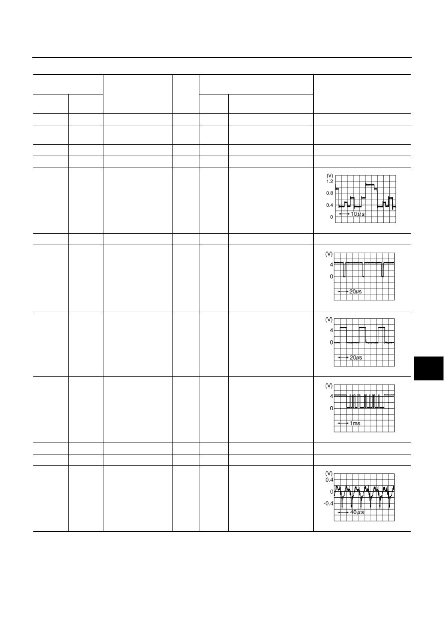
Terminals and Reference Value for Display

NKS0023L

Terminal 

(Wire color)

Item

Signal 

input/

output

Condition

Reference value

+

Ignition 

switch

Operation

1 (B)

Ground

Ground

ON

Approx. 0 V

2 (L/W)

Ground

Power supply 
(Inverter) 

Input

ON

Approx. 9 V

3 (L/Y)

Ground

Power supply (Signal) 

Input

ON

Approx. 9 V

4

Shield

6 (G/R)

Ground

RGB signal (G: green)

Input

ON

Start Confirmation/Adjust-
ment mode, and then dis-
play color bar by selecting 
“Display Color Spectrum 
Bar” on Display Diagnosis 
screen

7

Shield

8 (R)

Ground

Horizontal
synchronizing (HP) 
signal

Output

ON

9 (B)

Ground

RGB area (YS) signal

Input

ON

Set the selector lever in R 
position, and then display 
the rear view image

11 (B/W)

Ground

Communication signal
(DCU-DSP)

Input

ON

13 (P)

Ground

Ground (Inverter)

ON

Approx. 0 V

14 (P/L)

Ground

Ground (Signal)

ON

Approx. 0 V

15 (R)

Ground

Rear view  image
signal

Input

ON

Set the selector lever in R 
position, and then display 
the rear view image

SKIB7770E

SKIB3601E

SKIB3599E

SKIB3607E

SKIB3608E

AV-154

NAVIGATION SYSTEM

Revision: 2006 July

2007 Murano

17 (G/Y)

Ground

RGB signal (R: red)

Input

ON

Start Confirmation/Adjust-
ment mode, and then dis-
play color bar by selecting 
“Display Color Spectrum 
Bar” on Display Diagnosis 
screen

18 (G/O)

Ground

RGB signal (B: blue)

Input

ON

Start Confirmation/Adjust-
ment mode, and then dis-
play color bar by selecting 
“Display Color Spectrum 
Bar” on Display Diagnosis 
screen

19 (G)

Ground

RGB synchronizing 
signal

Input

ON

When displaying RGB 
image

20 (W)

Ground

Vertical
synchronizing (VP) 
signal

Output

ON

21

Shield

22 (L)

Ground

Communication signal
(DSP-DCU)

Output

ON

23

Shield

Terminal 

(Wire color)

Item

Signal 

input/

output

Condition

Reference value

+

Ignition 

switch

Operation

SKIB7769E

SKIB7771E

SKIB3603E

SKIB3598E

SKIB3606E

NAVIGATION SYSTEM

AV-155

C

D

E

F

G

H

I

J

L

M

A

B

AV

Revision: 2006 July

2007 Murano

Terminals and Reference Value for A/C and AV Switch

NKS0023M

Terminal

(Wire color)

Item

Signal 

input/

output

Condition

Reference value

+

Ignition 

switch

Operation

1 (Y)

Ground

Battery power supply

Input

OFF

Battery voltage

2 (P/B)

Ground

ACC power supply

Input

ACC

Battery voltage

3 (R/L)

Ground

Illumination signal

Input

ON

Lighting switch ON

Approx. 12 V

Lighting switch OFF

Approx. 0 V

4 (R/W)

Ground

Illumination  control 
signal

Input

ON

Illumination control switch is 
operated by lighting switch 
in ON position

Changes between approx. 0 and 
approx. 12 V

5 (B)

Ground

Ground

ON

Approx. 0 V

6 (L/G)

Ground

Communication
signal (+)

Input/

Output

ON

7

Shield

8 (L/R)

Ground

Communication
signal (–)

Input/

Output

ON

12 (R)

Ground

Remote control A

Input

ON

Press and hold MODE 
switch

Approx. 0 V

Press and hold SEEK UP 
switch

Approx. 1.7 V

Press and hold VOL UP 
switch

Approx. 3.3 V

Except for above

Approx. 5 V

13 (G)

Ground

Remote control B

Input

ON

Press and hold POWER 
switch

Approx. 0 V

Press and hold SEEK 
DOWN switch

Approx. 1.7 V

Press and hold VOL DOWN 
switch

Approx. 3.3 V

Except for above

Approx. 5 V

14 (B/W)

Ground

Remote control 
ground

ON

Approx. 0 V

16 (G/W)

Ground

Rear window defogger 
ON signal

Output

ON

Press and hold rear win-
dow defogger button

Approx. 0 V

Except for above

Approx. 5 V

SKIB7378E

SKIB7379E

AV-156

NAVIGATION SYSTEM

Revision: 2006 July

2007 Murano

Terminals and Reference Value for Rear View Camera Control Unit

NKS0023N

Terminal

(Wire color)

Item

Signal 

input/

output

Condition

Reference value

+

Ignition 

switch

Operation

1 (Y)

Ground

Battery power supply

Input

OFF

Battery voltage

2 (P/B)

Ground

ACC power supply

Input

ACC

Battery voltage

3 (B)

Ground

Ground

ON

Approx. 0 V

4 (G/W)

Ground

Reverse signal

Input

ON

Selector lever in R position

Approx. 12 V

Other than selector lever in 
R position

Approx. 0 V

5 (V/W)

Ground

Camera-connection 
recognition signal

Output

ON

Approx. 0 V

6 (O)

Data transmit/receive 
signal

8 (L)

Ground

Camera power supply

Output

ON

Set the selector lever in R 
position, and then display 
the rear view image

Approx. 6 V

9

Shield

10 (R)

Ground

Rear view image
signal

Input

ON

Set the selector lever in R 
position, and then display 
the rear view image

11

Shield

12 (P/L)

Ground

Rear view image
signal

Output

ON

Set the selector lever in R 
position, and then display 
the rear view image

SKIB3608E

SKIB3608E

NAVIGATION SYSTEM

AV-157

C

D

E

F

G

H

I

J

L

M

A

B

AV

Revision: 2006 July

2007 Murano

Special Note for Trouble Diagnosis

NKS002Q8

Prior to performing trouble diagnosis, make sure there are no corresponding description in the “Example of
Symptoms Possible No Malfunction”. Refer to 

AV-195, "Example of Symptoms Possible No Malfunction"

 .

On Board Self-Diagnosis Function

NKS0023O

DESCRIPTION

Trouble diagnosis function of navigation system has a Self Diagnosis mode by automatic operation and a
Confirmation/Adjustment mode by manual operation.

Self Diagnosis mode checks for connections between the units constituting this system, analyzes each
individual unit at the same time, and displays the results on the display.

Confirmation/Adjustment mode displays trouble diagnosis that require an operation and a judgment by a
human (auto-decision cannot be performed by the system), confirmation of preset value, and an error his-
tory.

DIAGNOSIS ITEM

Mode

Description

Self Diagnosis (DCU)

Display control unit diagnosis

Analyzes connection between the display control unit and each unit, and 
operation of each unit.

Self Diagnosis (NAVI)

NAVI control unit diagnosis (DVD-ROM drive will not be diagnosed 
when no DVD-ROM is in it.).

Analyzes connection between the NAVI control unit and the GPS 
antenna.

Confirmation/
Adjustment

Display Diagnosis

Color tone and shading of the display control unit-generated image can be 
checked by the display of a color bar and a gray scale.

Vehicle Signals

Diagnosis of signals that are input to display control unit can be performed 
for Vehicle Speed, IGN, Reverse and Light.

Auto Climate Control

Refer to 

ATC-47, "Self-diagnosis Function"

 .

Navigation

Display Diagnosis

Color tone and shading of the NAVI control unit-generated image can be 
checked by the display of a color bar and a gray scale.

Vehicle Signals

Diagnosis of signals that are input to NAVI control unit can be performed 
for Vehicle speed, Lights, Ignition and Reverse.

Navigation

Steering 
Angle
Adjustment

This mode is used to correct difference between actual turning angle of a 
vehicle and turning angle of the vehicle mark on the display.

Speed
Calibration

Under ordinary conditions, the navigation system distance measuring 
function will automatically compensate for minute decreases in wheel and 
tire diameter caused by tire wear or low-pressure. Speed Calibration can 
immediately restore system accuracy in cases such as when distance cal-
ibration is needed because of the use of tire chains.

Error History

Malfunctions that occurred in the past are displayed, along with the num-
ber of times each has occurred. Time and location when/where the errors 
occurred are also displayed.

Delete Unit Connection Log

Erase the connection history of unit and error history.

CAN DIAG SUPPOPT MONITOR

The transmitting/receiving of CAN communication can be monitored.

AV-158

NAVIGATION SYSTEM

Revision: 2006 July

2007 Murano

Self-Diagnosis Mode (DCU)

NKS0023P

OPERATION PROCEDURE

1.

Start the engine.

2.

Turn the audio system OFF.

3.

While pressing the “4” button, turn the volume control dial clock-
wise or counterclockwise for 30 clicks or more. (When the self-
diagnosis mode is started, a short beep will be heard.)

Shifting from current screen to previous screen is performed
by pressing “BACK” button.

4.

The initial trouble diagnosis screen will be shown, and items
“Self Diagnosis (DCU)”, “Self Diagnosis (NAVI)”, “Confirmation/
Adjustment” and “CAN DIAG SUPPORT MONITOR” will
become selective.

5.

Perform self-diagnosis by selecting the “Self Diagnosis (DCU)”.

Self-diagnosis screen is displayed, and then self-diagnosis
starts.

The bar graph visible below self-diagnosis screen displays
progress of the diagnosis.

6.

When the self-diagnosis completes, optional part confirmation
screen will be shown.

When connection of an optional part is judged error, a screen
to check if the optional part is actually fitted on the vehicle or
not will be shown. When fitted, select the switch of the part on
the screen and press “End”. Then the “SELF DIAGNOSIS”
screen will be shown.

When the optional part is connected normally, the switch for
the part will not appear on the screen.

SKIB7750E

SKIB7874E

SKIA4208E

SKIB7751E

NAVIGATION SYSTEM

AV-159

C

D

E

F

G

H

I

J

L

M

A

B

AV

Revision: 2006 July

2007 Murano

7.

On the diagnosis results screen, each unit name and connection
line will be colored according to the diagnosis result, as follows.

NOTE:

Satellite = Satellite radio tuner

DCU = Display control unit

Multifunction switch = A/C and AV switch

Navigation = NAVI control unit

GPS = GPS antenna

If multiple malfunctions occur at the same time for a single unit, the screen switch colors are determined
according to the following order of priority: red > yellow > gray.

8.

Select a switch on the diagnosis results screen, and comments
for the diagnosis results will be shown.

SELF-DIAGNOSIS RESULT
Quick Reference Table

1.

Select the applicable diagnosis number in the quick reference table of diagnosis result.

2.

Confirm the possible malfunction with the diagnosis table, and then perform inspection.

3.

Turn ignition switch OFF and perform self-diagnosis again.

When A/C and AV switch has a malfunction, the self-diagnosis cannot be started. Refer to 

AV-177,

"Unable to Operate System with A/C and AV Switch"

 .

When display has a malfunction, the self-diagnosis cannot be started. Refer to 

AV-179, "All Images Are

Not Displayed"

 .

Green

: No malfunctioning.

Gray

: Cannot be judged by self-diagnosis results.

Red

: Unit is malfunctioning.

SKIB7875E

SKIA4211E

Switch color

Screen switch

Diagnosis 

No.

DCU

Display

Audio Unit

Navigation

GPS

Satellite

Red

×

1

Gray

×

2

×

×

3

×

×

4

×

5

×

6

AV-160

NAVIGATION SYSTEM

Revision: 2006 July

2007 Murano

Self-Diagnosis Codes

Diagnosis 

No.

Possible cause

Action to take

1

Display control unit malfunction is detected.

Replace display control unit.

2

Malfunction is detected on communication signal between 
display control unit and display.

1. Check communication circuit between display control 

unit and display.

2. Check communication signal between display control 

unit and display.

3. If the results from the above checkup show no malfunc-

tion, replace either display control unit or display, and 
then start self-diagnosis.

4. If self-diagnosis results still show any malfunction, 

replace the other unit.

3

Audio unit power supply circuit malfunction is detected.

Malfunction is detected on communication signal 
between display control unit and audio unit.

1. Check audio unit power supply circuit.

2. Check communication circuit between display control 

unit and audio unit.

3. Check communication signal between display control 

unit and audio unit.

4. If the results from the above checkup show no malfunc-

tion, replace either display control unit or audio unit, and 
then start self-diagnosis.

5. If self-diagnosis results still show any malfunction, 

replace the other unit.

4

NAVI control unit power supply and ground circuit mal-
function is detected.

Malfunction is detected on communication signal 
between display control unit and NAVI control unit.

1. Check NAVI control unit power supply and ground cir-

cuit.

2. Check communication circuit between display control 

unit and NAVI control unit.

3. If the results from the above checkup show no malfunc-

tion, replace either display control unit or NAVI control 
unit, and then start self-diagnosis.

4. If self-diagnosis results still show any malfunction, 

replace the other unit.

5

GPS antenna connection malfunction is detected.

1. Check if GPS antenna feeder line is snapped or 

pinched.

2. If the results from the above checkup show no malfunc-

tion, replace GPS antenna, and then restart self-diagno-
sis.

3. If self-diagnosis results still show any malfunction, 

replace NAVI control unit.

6

Satellite radio tuner power supply and ground circuit 
malfunction is detected.

Malfunction is detected on communication signal 
between audio unit and satellite radio tuner.

1. Check satellite radio tuner power supply and ground cir-

cuit.

2. Check communication circuit between audio unit and 

satellite radio tuner.

3. Check communication signal between audio unit and 

satellite radio tuner.

4. If the results from the above checkup show no malfunc-

tion, replace either audio unit or satellite radio tuner, and 
then start self-diagnosis.

5. If self-diagnosis results still show any malfunction, 

replace the other unit.

NAVIGATION SYSTEM

AV-161

C

D

E

F

G

H

I

J

L

M

A

B

AV

Revision: 2006 July

2007 Murano

Self-Diagnosis Mode (NAVI)

NKS0023Q

OPERATION PROCEDURE

1.

Start the engine.

2.

Turn the audio system OFF.

3.

While pressing the “4” button, turn the volume control dial clock-
wise or counterclockwise for 30 clicks or more. (When the self-
diagnosis mode is started, a short beep will be heard.)

Shifting from current screen to previous screen is performed
by pressing “BACK” button.

4.

The initial trouble diagnosis screen will be shown, and items
“Self Diagnosis (DCU)”, “Self Diagnosis (NAVI)”, “Confirmation/
Adjustment” and “CAN DIAG SUPPORT MONITOR” will
become selective.

NOTE:
Select “Self Diagnosis (DCU)” when “Self Diagnosis (NAVI)” is
not available. Repair malfunctioning part.

5.

Perform self-diagnosis by selecting the “Self Diagnosis (NAVI)”.

Self-diagnosis screen is displayed, and then self-diagnosis
starts.

The bar graph visible below self-diagnosis screen displays
progress of the diagnosis.

6.

On the diagnosis results screen, each unit name and connection
line will be colored according to the diagnosis result, as follows.

NOTE:

Control unit = NAVI control unit

Only Control unit (NAVI control unit) is displayed in red.

If multiple malfunctions occur at the same time for a single unit, the screen switch colors are determined
according to the following order of priority: red > yellow > gray.

SKIB7750E

SKIB7874E

SKIB6972E

Diagnosis results

Unit

Connection line

Normal

Green

Green

Connection malfunction

Gray

Yellow

DVD-ROM drive undiagnosed

Gray

Green

DVD-ROM and DVD-ROM drive malfunction

Yellow

Green

Unit returned an error

Red

Green

SKIB7772E

AV-162

NAVIGATION SYSTEM

Revision: 2006 July

2007 Murano

7.

Select a switch on the diagnosis results screen, and comments
for the diagnosis results will be shown.

SKIB3659E

NAVIGATION SYSTEM

AV-163

C

D

E

F

G

H

I

J

L

M

A

B

AV

Revision: 2006 July

2007 Murano

SELF-DIAGNOSIS RESULT

Check the applicable display in the following table, and then repair the malfunctioning parts.

Quick Reference Table

Self-diagnosis result screen

Possible cause

Action to take

NAVI control unit malfunction is 
detected.

Replace NAVI control unit.
Refer to 

AV-198, "Removal and Installa-

tion of NAVI Control Unit"

 .

Malfunction is detected on DVD-
ROM drive pickup lens in NAVI con-
trol unit.

There is dirt and damage on the 
DVD-ROM.

1. Check if the inserted DVD-ROM is 

specified for this navigation system, 
and the DVD-ROM is dirty, scratched or 
warped.

2. If the results from the above checkup 

show no malfunction, insert the same 
DVD-ROM, and then restart self-diag-
nosis.

3. If self-diagnosis results still show any 

malfunction, replace NAVI control unit.

DVD-ROM not inserted is detected.

Insert DVD-ROM.

GPS antenna connection malfunction 
is detected.

1. Check if GPS antenna feeder line is 

snapped or pinched.

2. If the results from the above checkup 

show no malfunction, replace GPS 
antenna, and then restart self-diagno-
sis.

3. If self-diagnosis results still show any 

malfunction, replace NAVI control unit.

SKIB7773E

SKIB7774E

SKIB7775E

SKIB7776E

AV-164

NAVIGATION SYSTEM

Revision: 2006 July

2007 Murano

Confirmation/Adjustment Mode

NKS0023R

OPERATION PROCEDURE

1.

Start the engine.

2.

Turn the audio system OFF.

3.

While pressing the “4” button, turn the volume control dial clock-
wise or counterclockwise for 30 clicks or more. (When the self-
diagnosis mode is started, a short beep will be heard.)

Shifting from current screen to previous screen is performed
by pressing “BACK” button.

4.

The initial trouble diagnosis screen will be shown, and items
“Self Diagnosis (DCU)”, “Self Diagnosis (NAVI)”, “Confirmation/
Adjustment” and “CAN DIAG SUPPORT MONITOR” will
become selective.

5.

Select “Confirmation/Adjustment”.

6.

Each diagnosis is shown by selecting each screen switch on
Confirmation/Adjustment screen.

SKIB7750E

SKIB7874E

SKIA4220E

NAVIGATION SYSTEM

AV-165

C

D

E

F

G

H

I

J

L

M

A

B

AV

Revision: 2006 July

2007 Murano

DISPLAY DIAGNOSIS

Color tone and shading of the display control unit-generated image can be checked by the display of a color
bar and a gray scale.

If RGB signal is malfunctioning, the tint of the color bar display is as follows.

VEHICLE SIGNALS

A comparison check can be made of each actual vehicle signal and
the signals recognized by the display control unit.

NOTE:
In case of confirming light signal, set the following D/N mode to ON/
OFF of lighting switch (normal setting).

OFF: D (Day mode)

ON: N (Night mode)

Unless above setting, light signal (ON/OFF) may not be accurately
displayed.

R (red) signal error

: Light blue (Cyan) tint

G (green) signal error

: Purple (Magenta) tint

B (blue) signal error

: Yellow tint

SKIB7777E

SKIB7778E

Diagnosis item

Display

Condition

Remarks

Vehicle Speed

ON

When vehicle speed is more than 0 km/h (0 MPH)

Changes in indication may be delayed. 
This is normal.

OFF

When vehicle speed is 0 km/h (0 MPH)

Ignition switch in ACC position

IGN

ON

Ignition switch ON

OFF

Ignition switch ACC position

Reverse

ON

Selector lever in R position

Changes in indication may be delayed. 
This is normal.

OFF

Selector lever in any position other than R position

Ignition switch in ACC position

IVCS

OFF

This vehicle does not use it.

Light

ON

Lighting switch ON

OFF

Lighting switch OFF

AV-166

NAVIGATION SYSTEM

Revision: 2006 July

2007 Murano

AUTO CLIMATE CONTROL

Refer to 

ATC-47, "Self-diagnosis Function"

 .

NAVIGATION

Each diagnosis is shown by selecting each screen switch on Confir-
mation/Adjustment screen.

Display Diagnosis

Color tone and shading of the NAVI control unit-generated image can be checked by the display of a color bar
and a gray scale.

If RGB signal is malfunctioning, the tint of the color bar display is as follows.

SKIB7386E

R (red) signal error

: Light blue (Cyan) tint

G (green) signal error

: Purple (Magenta) tint

B (blue) signal error

: Yellow tint

SKIB6976E

NAVIGATION SYSTEM

AV-167

C

D

E

F

G

H

I

J

L

M

A

B

AV

Revision: 2006 July

2007 Murano

Vehicle Signals

A comparison check can be made of each actual vehicle signal and
the signals recognized by the NAVI control unit.

Navigation

Steering Angle Adjustment
The steering angle output value detected by the gyroscope can be
adjusted.

Speed Calibration
Usually the automatic distance correction function adjusts the mal-
function in distance caused by the tires wearing down or the tire
pressure change. If prompt adjustment is necessary when the tire
chains are installed, etc., perform this procedure.

SKIB6977E

Diagnosis item

Display

Condition

Remarks

Vehicle speed

ON

When vehicle speed is more than 0 km/h (0 MPH)

Changes in indication may be delayed. 
This is normal.

OFF

When vehicle speed is 0 km/h (0 MPH)

Ignition switch in ACC position

Lights

ON

Lighting switch ON

OFF

Lighting switch OFF

Ignition

ON

Ignition switch ON

OFF

Ignition switch ACC position

Reverse

ON

Selector lever in R position

Changes in indication may be delayed. 
This is normal.

OFF

Selector lever in any position other than R position

Ignition switch in ACC position

SKIB3684E

SKIB3685E

AV-168

NAVIGATION SYSTEM

Revision: 2006 July

2007 Murano

Error History

Diagnosis results of self-diagnosis depend on if any error occurred during the time after selecting “Self Diag-
nosis” until self-diagnosis results is displayed.
Meanwhile, when an error occurs before selecting “Self Diagnosis”, and if an error does not occur until self-
diagnosis results is displayed, a diagnosis result is judged as normal.
Consequently, a diagnosis needs to be performed with “Error History” for the past error that is not available
with self-diagnosis.
“Error History” displays the time and place of the most recent occurrence of that error. However, take note of
the following points.

Correct time of the error occurrence may not be displayed when the GPS antenna substrate within the
NAVI control unit has malfunctioned.

Place of the error occurrence is represented by the position of the vehicle mark at the time when the error
occurred. If the vehicle mark has deviated from the correct position, then the place of the error occurrence
may not be located correctly.

When the ignition switch is turned ON if the error is detected, the counter increases 1. Even if it is normal
when the ignition switch is turned ON the next time, the counter does not decrease.

The upper limit of the counter is 50. 51 or more is displayed as 50. It can be reset to 0 by “Delete log”
switch.

SKIB6978E


Content      ..     10      11      12      13     ..