Nissan Murano Z50 (2006 year). Manual - part 210


  Index      Manuals     Nissan Murano Z50 (2006 year) - Service and Repair Manual


Search            copyright infringement  


Content      ..     208      209      210      211     ..


Nissan Murano Z50 (2006 year). Manual - part 210


FRONT WIPER AND WASHER SYSTEM

WW-7

C

D

E

F

G

H

I

J

L

M

A

B

WW

Revision: 2006 August

2006 Murano

MIST OPERATION

When the wiper switch is turned to the mist position, wiper low speed operation cycles once and then stops.
For additional information about wiper operation under this condition. Refer to 

WW-5, "LOW SPEED WIPER

OPERATION"

 .

If the switch is held in the mist position, low speed operation continues.

FAIL-SAFE FUNCTION

If an abnormality occurs in CAN communications, IPDM E/R holds the condition just before fail-safe status is
initiated until ignition switch is turned OFF. (If wipers were operating in LO just before the initiation of fail-safe
status, they continue to operate in LO until ignition switch is turned OFF.) 

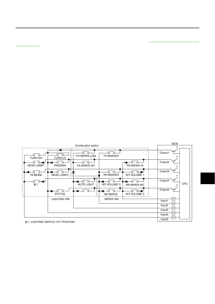
COMBINATION SWITCH READING FUNCTION
Description

BCM reads combination switch (wiper) status, and controls related systems such as head lamps and wip-
ers, according to the results.

BCM reads information of a maximum of 20 switches by combining five output terminals (OUTPUT 1-5)
and five input terminals (INPUT 1-5).

Operation Description

BCM activates transistors of output terminals (OUTPUT 1-5) periodically and, and allows current to flow in
turn.

If any (1 or more) switches are turned ON, circuit of output terminals (OUTPUT 1-5) and input terminals
(INPUT 1-5) becomes active.

At this time, transistors of output terminals (OUTPUT 1-5) are activated to allow current to flow. When volt-
age of input terminals (INPUT 1-5) corresponding to that switch changes, interface in BCM detects volt-
age change, and BCM determines that switch is ON.

PKID0853E

WW-8

FRONT WIPER AND WASHER SYSTEM

Revision: 2006 August

2006 Murano

BCM - Operation Table of Combination Switches

BCM reads operation status of combination switch using combinations shown in table below.

Sample Operation: (When Wiper Switch Turned to LOW Position)

When wiper switch is turned to LOW position, front wiper LOW contact in combination switch turns ON. At
this time if OUTPUT 1 transistor is activated, BCM detects that voltage changes in INPUT 3.

When BCM detects that voltage changes in INPUT 3 while OUTPUT 1 transistor is ON, it judges that front
wiper switch is in LOW position. Then BCM sends front wiper request signal (LO) to IPDM E/R using CAN
communication.

If BCM detects that voltage changes in INPUT 3 when OUTPUT 1 transistor is activated again, it recog-
nizes that wiper switch is still in LOW position.

NOTE:
Each OUTPUT terminal transistor is activated at 10 ms intervals. Therefore after switch is turned ON, electri-
cal loads are activated with time delay. But this time delay is so short that it cannot be detected by human
senses.

SKIA4959E

PKID0854E

FRONT WIPER AND WASHER SYSTEM

WW-9

C

D

E

F

G

H

I

J

L

M

A

B

WW

Revision: 2006 August

2006 Murano

Operation Mode

Combination switch reading function has operation modes shown below.

1.

Normal status

When BCM is not in sleep status, OUTPUT terminals (1-5) each turn ON-OFF every 10 ms.

2.

Sleep status

When BCM is in sleep status, transistors of OUTPUT (1 and 5) stop the output, and BCM enters low cur-
rent consumption mode. OUTPUT (2, 3, and 4) turn ON-OFF every 60 ms, and only input from light switch
system is accepted.

CAN Communication System Description

NKS001TS

CAN (Controller Area Network) is a serial communication line for real time application. It is an on-vehicle mul-
tiplex communication line with high data communication speed and excellent error detection ability. Many elec-
tronic control units are equipped onto a vehicle, and each control unit shares information and links with other
control units during operation (not independent). In CAN communication, control units are connected with 2
communication lines (CAN H line, CAN L line) allowing a high rate of information transmission with less wiring.
Each control unit transmits/receives data but selectively reads required data only.

CAN Communication Unit

NKS001TT

Refer to 

LAN-32, "CAN Communication Unit"

 .

PKIB6124E

WW-10

FRONT WIPER AND WASHER SYSTEM

Revision: 2006 August

2006 Murano

Schematic

NKS001TU

TKWB2614E

FRONT WIPER AND WASHER SYSTEM

WW-11

C

D

E

F

G

H

I

J

L

M

A

B

WW

Revision: 2006 August

2006 Murano

Wiring Diagram — WIPER —

NKS001TV

TKWB2615E

WW-12

FRONT WIPER AND WASHER SYSTEM

Revision: 2006 August

2006 Murano

TKWB2616E

FRONT WIPER AND WASHER SYSTEM

WW-13

C

D

E

F

G

H

I

J

L

M

A

B

WW

Revision: 2006 August

2006 Murano

TKWB2617E

WW-14

FRONT WIPER AND WASHER SYSTEM

Revision: 2006 August

2006 Murano

Terminals and Reference Values for BCM

NKS001TW

CAUTION:

Check combination switch system terminal waveform under the loaded condition with lighting
switch, turn signal switch and wiper switch OFF not to be fluctuated by overloaded.

Turn wiper dial position to 4 except when checking waveform or voltage of wiper dial position.
Wiper dial position can be confirmed on CONSULT-II. Refer to 

WW-19, "DATA MONITOR"

 .

Terminal 

No.

Wire 

color

Signal name

Measuring condition

Reference value

Ignition 

switch

Operation or condition

4

R/G

Combination 
switch input 3

ON

Lighting, turn, wiper 
switch
(Wiper intermittent 
dial position 4)

OFF

Approx. 0 V

Any of the conditions 
below

Front wiper switch MIST

Front wiper switch INT

Front wiper switch LO

Approx. 1.0 V

5

R/B

Combination 
switch input 2

ON

Lighting, turn, wiper 
switch

OFF
(Wiper intermittent dial 
position 4)

Approx. 0 V

Any of the conditions 
below

Front washer switch
(Wiper intermittent dial 
position 4)

Wiper intermittent dial 
position 1

Wiper intermittent dial 
position 5

Wiper intermittent dial 
position 6

Approx. 1.0 V

PKIB4959J

PKIB4959J

FRONT WIPER AND WASHER SYSTEM

WW-15

C

D

E

F

G

H

I

J

L

M

A

B

WW

Revision: 2006 August

2006 Murano

6

R/W

Combination 
switch input 1

ON

Lighting, turn, wiper 
switch

OFF
(Wiper intermittent dial 
position 4)

Approx. 0 V

Any of the conditions 
below

Front wiper switch HI
(Wiper intermittent dial 
position 4)

Wiper intermittent dial 
position 3

Approx. 1.0 V

Any of the conditions 
below

Wiper intermittent dial 
position 1 

Wiper intermittent dial 
position 2

Approx. 1.7 V

Any of the conditions 
below

Wiper intermittent dial 
position 6

Wiper intermittent dial 
position 7

Approx. 0.8 V

32

LG/B

Combination 
switch output 5

ON

Lighting, turn, wiper 
switch

OFF
(Wiper intermittent dial 
position 4)

Approx. 7.2 V

Any of the conditions 
below

Wiper intermittent dial 
position 1

Wiper intermittent dial 
position 2

Wiper intermittent dial 
position 6

Wiper intermittent dial 
position 7

Approx. 1.0 V

Terminal 

No.

Wire 

color

Signal name

Measuring condition

Reference value

Ignition 

switch

Operation or condition

PKIB4959J

PKIB4952J

PKIB4955J

PKIB4960J

PKIB4956J

WW-16

FRONT WIPER AND WASHER SYSTEM

Revision: 2006 August

2006 Murano

33

G/Y

Combination 
switch output 4

ON

Lighting, turn, wiper 
switch

OFF
(Wiper intermittent dial 
position 4)

Approx. 7.2 V

Any of the conditions 
below

Wiper intermittent dial 
position 1

Wiper intermittent dial 
position 5

Wiper intermittent dial 
position 6

Approx. 1.2 V

34

LG/R

Combination 
switch output 3

ON

Lighting, turn, wiper 
switch

OFF
(Wiper intermittent dial 
position 4)

Approx. 7.2 V

Any of the conditions 
below

Wiper intermittent dial 
position 1

Wiper intermittent dial 
position 2

Wiper intermittent dial 
position 3

Approx. 1.2 V

35

G/B

Combination 
switch output 2

ON

Lighting, turn, wiper 
switch
(Wiper intermittent 
dial position 4)

OFF

Approx. 7.2 V

Any of the conditions 
below

Front wiper switch INT

Front wiper switch HI

Approx. 1.2 V

Terminal 

No.

Wire 

color

Signal name

Measuring condition

Reference value

Ignition 

switch

Operation or condition

PKIB4960J

PKIB4958J

PKIB4960J

PKIB4958J

PKIB4960J

PKIB4958J

FRONT WIPER AND WASHER SYSTEM

WW-17

C

D

E

F

G

H

I

J

L

M

A

B

WW

Revision: 2006 August

2006 Murano

Terminals and Reference Values for IPDM E/R

NKS001TX

How to Proceed with Trouble Diagnosis

NKS001TY

1.

Confirm the symptoms and customer complaint.

2.

Understand operation description and function description. Refer to 

WW-4, "System Description"

 .

3.

Perform the preliminary check. Refer to 

WW-18, "Preliminary Check"

 .

4.

Check symptom and repair or replace the cause of malfunction.

5.

Does the front wiper and washer operate normally? If YES, GO TO 6. If NO, GO TO 4.

36

L/W

Combination 
switch output 1

ON

Lighting, turn, wiper 
switch
(Wiper intermittent 
dial position 4)

OFF

Approx. 7.2 V

Any of the conditions 
below

Front wiper switch MIST

Front wiper switch LO

Front washer switch

Approx. 1.2 V

38

R

Ignition switch 
(ON)

ON

Battery voltage

39

L

CAN 


H

40

Y

CAN 


L

42

GR

Battery power 
supply

OFF

Battery voltage

52

B

Ground

ON

Approx. 0 V

55

W/B

Battery power 
supply

OFF

Battery voltage

Terminal 

No.

Wire 

color

Signal name

Measuring condition

Reference value

Ignition 

switch

Operation or condition

PKIB4960J

PKIB4958J

Terminal 

No.

Wire 

color

Signal name

Measuring condition

Reference value

Ignition 

switch

Operation or condition

21

L

Low speed signal

ON

Wiper switch

OFF

Approx. 0 V

LOW

Battery voltage

31

L/B

High speed signal

ON

Wiper switch

OFF

Approx. 0 V

HI

Battery voltage

32

L/Y

Wiper auto stop signal

ON

Wiper operating

Battery voltage

Wiper stopped

Approx. 0 V

38

B

Ground

ON

Approx. 0 V

44

R/W

Washer pump power supply 

ON

Battery voltage

48

L

CAN 


H

49

Y

CAN 


L

60

B

Ground

ON

Approx. 0 V

WW-18

FRONT WIPER AND WASHER SYSTEM

Revision: 2006 August

2006 Murano

6.

INSPECTION END

Preliminary Check

NKS001TZ

CHECK POWER SUPPLY AND GROUND CIRCUIT

1. 

CHECK FUSES AND FUSIBLE LINK

Check for blown fuses and fusible link.

Refer to 

WW-11, "Wiring Diagram — WIPER —"

 .

OK or NG

OK

>> GO TO 2.

NG

>> If fuse or fusible link is blown, be sure to eliminate cause of malfunction before installing new fuse

or fusible link. Refer to 

PG-3, "POWER SUPPLY ROUTING CIRCUIT"

 .

2. 

CHECK POWER SUPPLY CIRCUIT

1.

Turn ignition switch OFF.

2.

Disconnect BCM connector.

3.

Check voltage between BCM harness connector and ground.

OK or NG

OK

>> GO TO 3.

NG

>> Repair harness or connector.

3. 

CHECK GROUND CIRCUIT

Check continuity between BCM harness connector and ground.

OK or NG

OK

>> INSPECTION END

NG

>> Repair harness or connector.

Unit

Power source

Fuse and fusible link No.

BCM

Battery

F

18

Ignition ON or START

1

Front wiper motor, front wiper relay, front wiper high relay

Battery

73

Front and rear washer pump via combination switch

Ignition ON or START

84

(+)

(

)

Ignition switch position

BCM con-

nector

Terminal

OFF

ON

M34

38

Ground

Approx. 0 V

Battery voltage

M35

42

Battery voltage

Battery voltage

55

Battery voltage

Battery voltage

PKIB5199E

BCM connector

Terminal

Ground

Continuity

M35

52

Yes

PKIB5198E

FRONT WIPER AND WASHER SYSTEM

WW-19

C

D

E

F

G

H

I

J

L

M

A

B

WW

Revision: 2006 August

2006 Murano

CONSULT-II Functions (BCM)

NKS001U0

CONSULT-II can display each diagnostic item using the diagnostic test modes shown following.

CONSULT-II BASIC OPERATION

Refer to 

GI-38, "CONSULT-II Start Procedure"

 .

WORK SUPPORT
Operation Procedure

1.

Touch “WIPER” on “SELECT TEST ITEM” screen.

2.

Touch “WORK SUPPORT” on “SELECT DIAG MODE” screen.

3.

Touch “WIPER SPEED SETTING” on “SELECT WORK ITEM” screen.

4.

Touch “START”.

5.

Touch “CHANGE SETT”.

6.

The setting will be changed and “CUSTOMIZING COMPLETED” will be displayed.

7.

Touch “END”.

Display Item List

*: When performed “RESET SETTING VALUE” on the BCM “WORK SUPPORT”, change setting value to the default value. Refer to

BCS-13, "WORK SUPPORT"

 .

DATA MONITOR
Operation Procedure

1.

Touch “WIPER” on “SELECT TEST ITEM” screen.

2.

Touch “DATA MONITOR” on “SELECT DIAG MODE” screen.

3.

Touch either “ALL SIGNALS” or “SELECTION FROM MENU” on “SELECT MONITOR ITEM” screen.

4.

When “SELECTION FROM MENU” is selected, touched items to be monitored. If “ALL SIGNALS” is
selected, all items will be monitored.

5.

Touch “START”.

6.

Touch “RECORDING START” while monitoring to record the status of the item being monitored. To stop
recording, touch “RECORDING STOP”.

Display Item List

BCM diagnosis position

Diagnosis mode

Description

WIPER

WORK SUPPORT

Changes the setting for each function.

DATA MONITOR

Displays BCM input data in real time.

ACTIVE TEST

Device operation can be checked by applying a drive signal to device.

BCM

SELF-DIAG RESULTS

BCM performs self-diagnosis of CAN communication.

CAN DIAG SUPPORT MNTR

The result of transmit/receive diagnosis of CAN communication can be read.

Item

Description

CONSULT-II

Setting value*

WIPER SPEED SETTING

Vehicle speed sensing type wiper control mode can be changed in 
this mode. Selects vehicle speed sensing type wiper control mode 
between two ON/OFF.

ON

Default

OFF

Factory setting

ALL SIGNALS

Monitors all the signals.

SELECTION FROM MENU

Selects items and monitors them.

Monitor item

Contents

IGN ON SW

“ON/OFF”

Displays “ignition switch ON (ON)/Other OFF or ACC (OFF)” status as judged from ignition 
switch signal.

IGN SW CAN

“ON/OFF”

Displays “ignition switch ON (ON)/Other OFF or ACC (OFF)” status as judged from CAN 
communication signal.

FR WIPER HI

“ON/OFF”

Displays “FRONT WIPER HI (ON)/Other (OFF)” status as judged from wiper switch signal.

WW-20

FRONT WIPER AND WASHER SYSTEM

Revision: 2006 August

2006 Murano

NOTE:
This item is displayed, but cannot be monitored.

ACTIVE TEST
Operation Procedure

1.

Touch “WIPER” on “SELECT TEST ITEM” screen.

2.

Touch “ACTIVE TEST” on “SELECT DIAG MODE” screen.

3.

Touch items to be tested, and check operation.

4.

During operation check, touching “OFF” deactivates operation.

Display Item List

FR WIPER LOW

“ON/OFF”

Displays “FRONT WIPER LOW (ON)/Other (OFF)” status as judged from wiper switch sig-
nal.

FR WIPER INT

“ON/OFF”

Displays “FRONT WIPER INT (ON)/Other (OFF)” status as judged from wiper switch sig-
nal.

FR WASHER SW

“ON/OFF”

Displays “FRONT WASHER Switch (ON)/Other (OFF)” status as judged from wiper switch 
signal.

INT VOLUME

“1 - 7”

Displays intermittent operation dial position setting (1 - 7) as judged from wiper switch sig-
nal.

FR WIPER STOP

“ON/OFF”

Displays “Stopped (ON)/Operating (OFF)” status as judged from the auto-stop signal.

VEHICLE SPEED

 “km/h” 

Displays vehicle speed status as judged from vehicle speed signal.

RR WIPER ON


“ON/OFF”

Displays “Rear Wiper ON (ON)/Other (OFF)” status as judged from wiper switch signal.

RR WIPER INT

“ON/OFF”

Displays “Rear Wiper INT (ON)/Other (OFF)” status as judged from wiper switch signal.

RR WASHER SW

“ON/OFF”

Displays “Rear Washer Switch (ON)/Other (OFF)” status as judged from wiper switch sig-
nal.

RR WIPER STOP

“ON/OFF”

Displays “Rear Wiper Stop (ON)/Other (OFF)” status, as judged from wiper switch signal.

RR WIPER STP2 

NOTE

“OFF”

Monitor item

Contents

Test item

Display on CONSULT-II screen

Description

Front wiper output

FR WIPER

With a certain operation (OFF, HI, LO, INT), the front wiper can be operated.

Rear wiper output

RR WIPER

Rear wiper can be operated by any ON-OFF operation.

FRONT WIPER AND WASHER SYSTEM

WW-21

C

D

E

F

G

H

I

J

L

M

A

B

WW

Revision: 2006 August

2006 Murano

CONSULT-II Functions (IPDM E/R)

NKS001U1

CONSULT-II can display each diagnostic item using the diagnostic test modes shown following.

CONSULT-II BASIC OPERATION

Refer to 

GI-38, "CONSULT-II Start Procedure"

 .

DATA MONITOR
Operation Procedure

1.

Touch “DATA MONITOR” on “SELECT DIAG MODE ” screen.

2.

Touch “ALL SIGNALS”, “MAIN SIGNALS”, or “SELECTION FROM MENU” on the “SELECT MONITOR
ITEM” screen.

3.

Touch the required monitoring item on “SELECTION FROM MENU”. In “ALL SIGNALS”, all items are
monitored. In “MAIN SIGNALS”, predetermined items are monitored.

4.

Touch “START”.

5.

Touch “RECORD” while monitoring to record the status of the item being monitored. To stop recording,
touch “STOP”.

All Signals, Main Signals, Selection From Menu

NOTE:
Perform monitoring of IPDM E/R data with the ignition switch ON. When the ignition switch is at ACC, the dis-
play may not be correct.

ACTIVE TEST
Operation Procedure

1.

Touch “ACTIVE TEST” on “SELECT DIAG MODE” screen.

2.

Touch item to be tested, and check operation.

3.

Touch “START”.

4.

Touch “OFF” while testing to stop the operation.

Diagnosis Mode

Description

SELF

DIAG RESULTS

Refer to 

PG-19, "SELF-DIAG RESULTS"

 .

DATA MONITOR

The input/output data of IPDM E/R is displayed in real time.

CAN DIAG SUPPORT MNTR

The result of transmit/receive diagnosis of CAN communication can be read.

ACTIVE TEST

IPDM E/R sends a drive signal to electronic components to check their operation.

ALL SIGNALS

Monitors all items.

MAIN SIGNALS

Monitor the predetermined item.

SELECTION FROM MENU

Selects items and monitors them.

Item name

CONSULT-II 

screen display

Display or unit

Monitor item selection

Description

ALL

SIGNALS

MAIN 

SIGNALS

SELECTION 

FROM 
MENU

FR wiper request

FR WIP REQ

STOP/LOW/HI

×

×

×

Signal status input from BCM

Wiper auto stop

WIP AUTO STOP

ACT P/STOP P

×

×

×

Output status of IPDM E/R

Wiper protection

WIP PROT

OFF/BLOCK

×

×

×

Control status of IPDM E/R

Test item

CONSULT-II screen display

Description

Front wiper (HI, LO) output

FRONT WIPER

With a certain operation (OFF, HI ON, LO ON), the front wiper relay 
(Lo, Hi) can be operated.

WW-22

FRONT WIPER AND WASHER SYSTEM

Revision: 2006 August

2006 Murano

Front Wiper Does Not Operate

NKS001U2

CAUTION:

During IPDM E/R fail-safe control, front wipers may not operate. Refer to 

PG-17, "CAN COMMUNICA-

TION LINE CONTROL"

  in “PG IPDM E/R” to make sure that it is not in fail-safe status.

1. 

ACTIVE TEST

With CONSULT-ll

1.

Select “IPDM E/R” by CONSULT-II, and select “ACTIVE TEST”
on “SELECT DIAG MODE” screen.

2.

Select “FRONT WIPER” on “SELECT TEST ITEM” screen.

3.

Touch “LO” or “HI” screen.

Without CONSULT-ll

Start up auto active test. Refer to 

PG-21, "Auto Active Test"

 .

Does front wiper operate normally?

YES

>> GO TO 5.

NO

>> GO TO 2.

2. 

CHECK FRONT WIPER CIRCUIT

1.

Turn ignition switch OFF.

2.

Disconnect IPDM E/R connector and front wiper motor connec-
tor.

3.

Check continuity between IPDM E/R harness connector and
front wiper motor harness connector.

4.

Check continuity between IPDM E/R harness connector and
ground.

OK or NG

OK

>> GO TO 3.

NG

>> Repair harness or connector.

3. 

CHECK GROUND CIRCUIT

Check continuity between front wiper motor harness connector E22
terminal 1 and ground.

OK or NG

OK

>> GO TO 4.

NG

>> Repair harness or connector.

SKIA3486E

IPDM E/R

Front wiper motor

Continuity

Connector

Terminal

Connector

Terminal

E7

21

E22

3

Yes

31

2

IPDM E/R

Ground

Continuity

Connector

Terminal

E7

21

No

31

PKIB2186E

1 – Ground

: Continuity should exist.

PKIA6406E


Content      ..     208      209      210      211     ..