Nissan Murano Z50 (2006 year). Manual - part 205
TRANSFER ASSEMBLY
TF-55
C
E
F
G
H
I
J
K
L
M
A
B
TF
Revision: 2006 August
2006 Murano
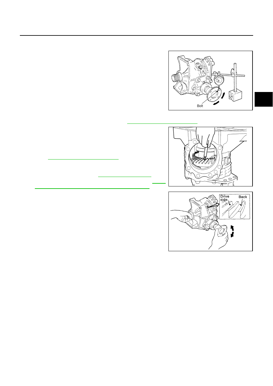
ASSEMBLY INSPECTION
Backlash
1.
Install a bolt to the companion flange.
2.
Fit a dial indicator onto the bolt.
3.
Measure the circumference backlash of the companion flange,
and make sure it satisfies the standard below.
●
If measured value is out of the specification, disassemble it to
check and adjust each part.
Tooth Contact
1.
Remove the pinion sleeve assembly. Refer to
TF-59, "Pinion Sleeve Assembly"
2.
Apply red lead to the drive gear.
CAUTION:
Apply red lead to both the faces of 3 to 4 gears at 4 loca-
tions evenly spaced on the drive gear.
3.
Install the pinion sleeve shims and pinion sleeve assembly.
Refer to
TF-69, "Pinion Sleeve Assembly"
.
4.
Remove the plug on the upper side of the transfer case.
When installing plug, apply sealant on screw part, and tighten it
at the specified torque. Refer to
●
Use Genuine Silicone RTV or equivalent. Refer to
"Recommended Chemical Products and Sealants"
5.
Rotate the companion flange back and forth several times, and
check the drive pinion gear to drive gear tooth contact by view-
ing from the plug hole.
Backlash
: 0.13 - 0.19 mm (0.0051 - 0.0075 in)
SDIA1801E
SDIA1524E
SDIA1802E