Nissan Murano Z50 (2006 year). Manual - part 198
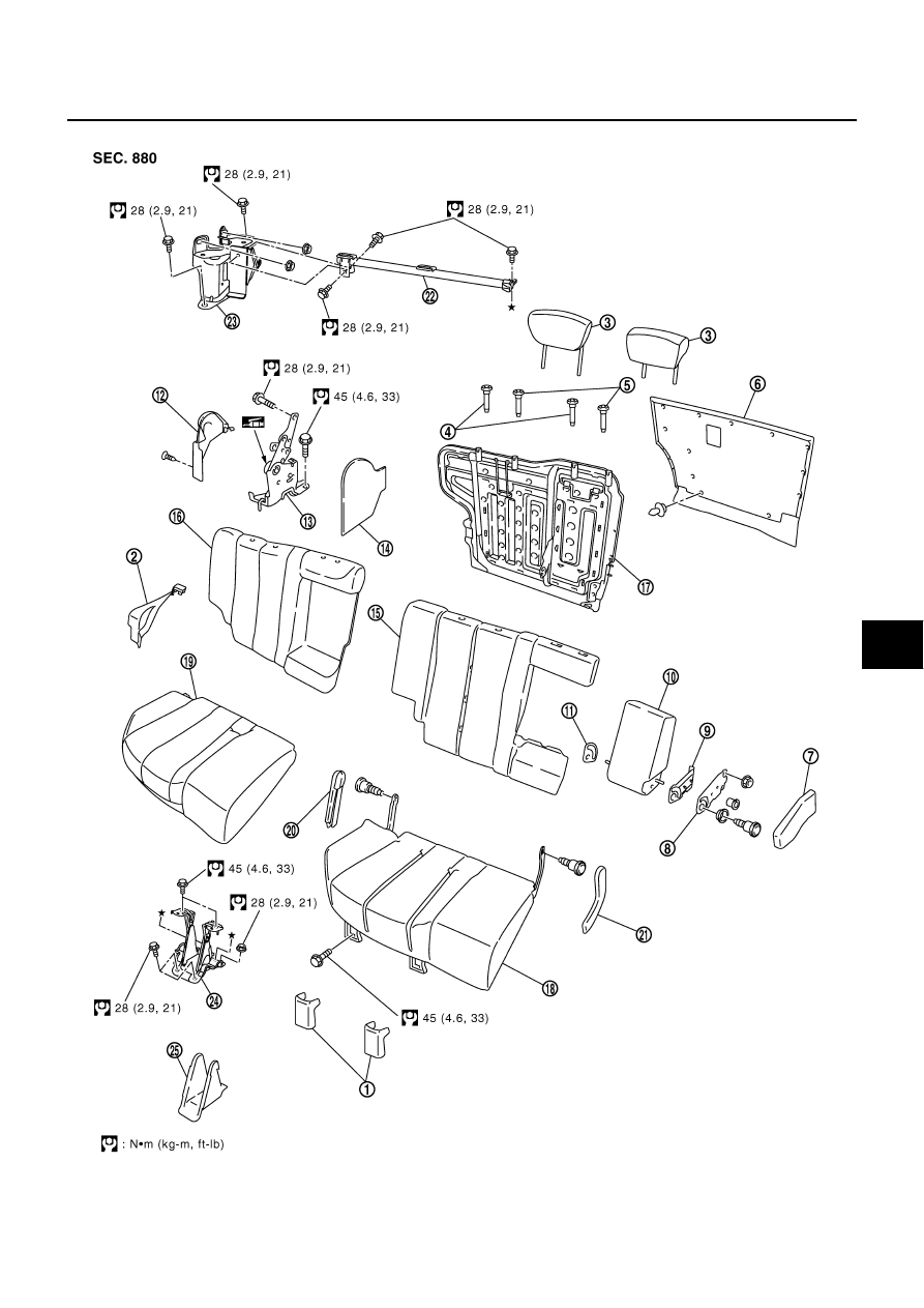
REAR SEAT
SE-111
C
D
E
F
G
H
J
K
L
M
A
B
SE
Revision: 2006 August
2006 Murano
RH SIDE SEAT
PIIB4962E
|
|
|
REAR SEAT SE-111 C D E F G H J K L M A B SE Revision: 2006 August 2006 Murano RH SIDE SEAT PIIB4962E |