Nissan Murano Z50 (2006 year). Manual - part 183


  Index      Manuals     Nissan Murano Z50 (2006 year) - Service and Repair Manual


Search            copyright infringement  


Content      ..     181      182      183      184     ..


Nissan Murano Z50 (2006 year). Manual - part 183


SUNROOF

RF-11

C

D

E

F

G

H

J

K

L

M

A

B

RF

Revision: 2006 August

2006 Murano

SUNROOF OPERATION

The ground is supplied to the terminals 1, 2, 3, 4 and 5 of sunroof motor assembly by combining the 1, 2, 3, 4,
5 and 6 terminals of sunroof switch.
Sunroof motor assembly operates sunroof in TILT or SLIDE by combining signals of the 1, 2, 3, 4 and 5 termi-
nals.
Ground is supplied

to sunroof switch terminal 6

through body ground M14 and M78.

SUNROOF SWITCH READING FUNCTION

1.

Description

Sunroof switch reads sunroof switch status, and controls various electrical components according to
the results.

Sunroof switch reads information of 8 switches by combining five terminals.
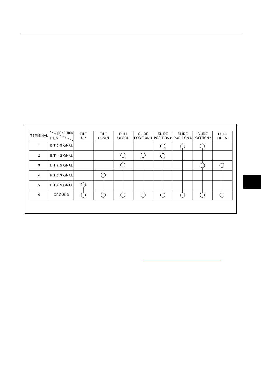
2.

Sunroof motor assembly - Operation table of sunroof switch
Reads operation status of sunroof switch by the combination shown in the table.

RETAINED POWER OPERATION

When the ignition switch is turned to “OFF” position from “ON” or “START” position, power is supplied for 45
seconds.

to sunroof motor assembly terminal 9

from BCM terminal 53.

When power is supplied, the sunroof can be operated.
The retained power operation is canceled when the driver or passenger side door is opened.
RAP signal period can be changed by CONSULT-II. Refer to 

RF-18, "CONSULT-II Function (BCM)"

 .

PIIA4539E

RF-12

SUNROOF

Revision: 2006 August

2006 Murano

ANTI-PINCH FUNCTION

The CPU of sunroof motor monitors the sunroof motor operation and the sunroof position (fully-closed or
other) by the signals from sunroof motor.
When sunroof motor detects an interruption during the following slid close and tilt down operation, sunroof
switch controls the motor for open and the sunroof will operate until full up position (when tilt down operate) or
125 mm (4.92 in) or more in an open direction (when slide close operate):

close operation and tilt down when ignition switch is in the “ON” position

close operation and tilt down during retained power operation.

MEMORY RESET PROCEDURE

1.

Please observe the following instructions while confirming the sunroof operation.

NOTE:
Do not disconnect the electronic power while the sunroof is operating or within 5 seconds after the sunroof
stops. (to wipe-out the memory of lid position and operating friction.)

2.

Initialization of system should be conducted after the following conditions.

When the battery is out or connector is disconnected while sunroof is operating or within 5 seconds
after sunroof stops.

When the sunroof motor is changed.

When an emergency handle is used.

When the sunroof does not operate normally. (Incomplete initialization conditions)

INITIALIZATION PROCEDURE

If the sunroof does not close or open automatically, use the following procedure to return sunroof operation to
normal.

1.

Close the sunroof if it is not in the closed position. It may be necessary to repeatedly push the switch to
close the sunroof. 

2.

Press and hold the TILT UP switch. Do not release the switch, keep pressure on it. After 10 seconds of
depressing, the sunroof will tilt up, then tilt down. Release the button.

3.

Press and hold the TILT UP switch again. Do not release the switch, keep pressure on it. While depress-
ing the switch, the sunroof will “Slide open” “Slide close” “Tilt up” “Tilt down”. Release the button after the
sunroof “Tilts down” and stops.

4.

Initializing procedure is complete. Confirm proper operation of the sunroof (slide open, slide close, tilt up,
tilt down.)

SUNROOF

RF-13

C

D

E

F

G

H

J

K

L

M

A

B

RF

Revision: 2006 August

2006 Murano

CAN Communication System Description

NIS001CV

CAN (Controller Area Network) is a serial communication line for real time application. It is an on-vehicle mul-
tiplex communication line with high data communication speed and excellent error detection ability. Many elec-
tronic control units are equipped onto a vehicle, and each control unit shares information and links with other
control units during operation (not independent). In CAN communication, control units are connected with 2
communication lines (CAN H line, CAN L line) allowing a high rate of information transmission with less wiring.
Each control unit transmits/receives data but selectively reads required data only.

CAN Communication Unit

NIS001CW

Refer to 

LAN-32, "CAN Communication Unit"

RF-14

SUNROOF

Revision: 2006 August

2006 Murano

Wiring Diagram — SROOF —

NIS001CX

TIWB0807E

SUNROOF

RF-15

C

D

E

F

G

H

J

K

L

M

A

B

RF

Revision: 2006 August

2006 Murano

TIWB0808E

RF-16

SUNROOF

Revision: 2006 August

2006 Murano

Terminals and Reference Value for BCM

NIS001CY

():Models without intelligent key

Terminals and Reference Value for Sunroof Motor Assembly

NIS001CZ

Terminal

Wire 

color

Signal name

Signal 

input/

output

Measuring condition

Voltage (V)

(Approx.)

Ignition 

switch

Operation or condition

12

R/G

(R)

Front door switch
passenger side

Input

OFF

OPEN (ON)

0

CLOSE (OFF)

Battery voltage

38

R

Ignition switch ON or 
START

Input

ON

Ignition switch (ON or START posi-
tion)

Battery voltage

42

GR

Battery power supply

Input

OFF

Battery voltage

52

B

Ground (power)

ON

0

53

W/L

RAP signal

Output

Ignition switch ON

Battery voltage

Within 45 seconds after ignition 
switch is turned to OFF position

Battery voltage

Within approx.45 seconds after igni-
tion switch OFF while front door LH 
or RH is open

0

54

W/R

Power window power 
supply

Output

ON

Battery voltage

55

W/B

Battery power supply 

Input

OFF

Battery voltage

62

SB

Front door switch
driver side

Input

OFF

OPEN (ON)

0

CLOSE (OFF)

Battery voltage

Termi-

nal

Wire 

color

Signal name

Sig-

nal 

input/

output

Measuring condition

Voltage (V)

(Approx.)

Igni-

tion 

switch

Operation or condition

1

V

Sunroof switch 
(BIT 4) signal

Input

ON

Sunroof switch in following position

TILT UP

0

Other than above

Battery voltage

2

G

Sunroof switch 
(BIT 0) signal

Input

ON

Sunroof switch in following position

SLIDE POSITION 2

SLIDE POSITION 3

SLIDE POSITION 4

0

Other than above

Battery voltage

3

R

Sunroof switch 
(BIT 1) signal

Input

ON

Sunroof switch in following position

FULL CLOSE 

SLIDE POSITION 1

SLIDE POSITION 2

0

Other than above

Battery voltage

4

Y

Sunroof switch 
(BIT 2) signal

Input

ON

Sunroof switch in following position

FULL CLOSE

FULL OPEN

SLIDE POSITION 4

0

Other than above

Battery voltage

5

O

Sunroof switch 
(BIT 3) signal

Input

ON

Sunroof switch in following position

TILT DOWN

0

Other than above

Battery voltage

SUNROOF

RF-17

C

D

E

F

G

H

J

K

L

M

A

B

RF

Revision: 2006 August

2006 Murano

Work Flow

NIS001D0

1.

Check the symptom and customer's requests.

2.

Understand the outline of system. Refer to 

RF-10, "System Description"

 .

3.

According to the trouble diagnosis chart, repair or replace the cause of the malfunction. Refer to 

RF-20,

"Trouble Diagnosis Chart by Symptom"

 .

4.

Does power window system operate normally? If Yes, GO TO 5, If No, GO TO 3.

5.

INSPECTION END.

7

L

Power window 
power supply 

Input

OFF

Battery voltage

8

SB

Vehicle speed 
signal (2-pulse)

Input

ON

Speedometer operated [When vehicle 
speed is approx.40km/ h (25MPH)]

9

W

RAP signal

Input

ON

Ignition switch ON

Battery voltage

Within 45 seconds after ignition switch is 
turned to OFF position

Battery voltage

Within approx.45 seconds after ignition 
switch OFF while front door LH or RH is 
open 

0

10

B

Ground

ON

0

Termi-

nal

Wire 

color

Signal name

Sig-

nal 

input/

output

Measuring condition

Voltage (V)

(Approx.)

Igni-

tion 

switch

Operation or condition

ELF1080D

RF-18

SUNROOF

Revision: 2006 August

2006 Murano

CONSULT-II Function (BCM)

NIS001D1

CAUTION:

If CONSULT-II is used with no connection of CONSULT-II CONVERTER, malfunction might be detected
in self-diagnosis depending on control unit which carry out CAN communication.

“RETAINED PWR”

1.

Turn ignition switch “OFF”.

2.

Connect “CONSULT-II” to the data link connector.

3.

Turn ignition switch “ON”.

4.

Touch “START (NISSAN BASED VHCL)”.

5.

Touch “BCM”.
If “BCM” is not indicated, go to Refer to “CONSULT-II Data Link
Connector (DLC) Circuit”.

6.

Touch “RETAINED PWR”.

PHIA0096E

BCIA0029E

BCIA0030E

LIIA0163E

SUNROOF

RF-19

C

D

E

F

G

H

J

K

L

M

A

B

RF

Revision: 2006 August

2006 Murano

7.

Select diagnosis mode. “DATA MONITOR”, “ACTIVE TEST” and
“WORK SUPPORT” are available.

Data Monitor

NIS001D2

Active Test

NIS001D3

Work Support 

NIS001D4

BCIA0031E

Monitored item

Description

IGN ON SW

Indicates [ON/OFF] condition of ignition switch.

DOOR SW-DR

Indicates [ON/OFF] condition of driver side door switch.

DDOR SW-AS

Indicates [ON/OFF] condition of passenger side door switch.

Test item

Description

RETAINED PWR

This test is able to supply RAP signal (power) from BCM to power window system and 
power sunroof system. Those systems can be operated when turning on “RETAINED 
PWR” on CONSULT-II screen even if the ignition switch is turned OFF.

NOTE:
During this test, CONSULT-II can be operated with ignition switch in “OFF” 
position.“RETAINED PWR” should be turned “ON” or “OFF” on CONLUST-II 
screen when ignition switch in ON. Then turn ignition switch OFF for checking 
retained power operation. CONSULT-II might be stuck if “RETAINED PWR” is 
turned to “ON” or “OFF” on CONSULT-II screen when ignition switch is OFF.

Work item

Description

RETAINED PWR SET

RAP signal’s power supply period can be changed by mode setting. Selects RAP sig-
nal’s power supply period between two steps.

MODE 1 (45 sec.) / MODE 2 (OFF) / MODE 3 (2 min.)

RF-20

SUNROOF

Revision: 2006 August

2006 Murano

Trouble Diagnosis Chart by Symptom

NIS001D5

Check BCM Power Supply and Ground Circuit

NIS001D6

First perform the “SELF-DIAG RESULTS” in “BCM” with CONSULT-II, then perform the each trouble
diagnosis of malfunction system indicated “SELF-DIAG RESULTS” of “BCM”. Refer to 

BCS-13, "CAN

Communication Inspection Using CONSULT-II (Self-Diagnosis)"

 .

1. 

CHECK FUSE 

Check 10A fuse [No.1, located in fuse block (J/B)]

Check 10A fuse [No. 18, located in fuse block (J/B)]

Check 50A fusible link (letter F,   located in the fuse and fusible link box).

NOTE:
Refer to 

RF-10, "Component Parts and Harness Connector Location"

 .

OK or NG

OK

>> GO TO 2.

NG

>> If fuse is blown, be sure to eliminate cause of malfunction before installing new fuse. Refer to 

PG-

3, "POWER SUPPLY ROUTING CIRCUIT"

Symptom

Diagnostic procedure and repair order

Refer to page

Sunroof does not operate.

1. Check BCM power supply and ground circuit.

RF-20

2. Check sunroof motor assembly power supply and 
ground circuit.

RF-22

3. Check sunroof switch circuit 9.

RF-29

4. Replace the sunroof motor assembly.

RF-44

Sunroof alone does not go to full close position.

1. Check sunroof switch circuit 1.

RF-24

Sunroof alone does not go to slide position 1.

1. Check sunroof switch circuit 2.

RF-25

Sunroof alone does not go to slide position 2.

1. Check sunroof switch circuit 3.

RF-25

Sunroof alone does not go to slide position 3.

1. Check sunroof switch circuit 4.

RF-26

Sunroof alone does not go to slide position 4.

1. Check sunroof switch circuit 5.

RF-27

Sunroof alone does not go to full open position.

1. Check sunroof switch circuit 6.

RF-27

Sunroof alone does not operate tilt up.

1. Check sunroof switch circuit 7.

RF-28

Sunroof alone does not operate tilt down.

1. Check sunroof switch circuit 8.

RF-29

Sunroof does not go to slide position 2, 3 and 4.

1. Check sunroof switch circuit 10.

RF-31

Sunroof does not go to full closed and slide position 1, 2.

1. Check sunroof switch circuit 11.

RF-32

Sunroof does not go to full close, full open and slide posi-
tion 4.

1. Check sunroof switch circuit 12.

RF-33

Retained power operation does not operate properly.

1. Check the retained power operation mode setting.

RF-18

2. Check door switch.

RF-34

3. Check BCM.

RF-23

4. Replace sunroof motor assembly.

RF-44

Motor does not stop at the sunroof fully -open or fully- 
closed position.

1. Check initialization procedure.

RF-12

2. Replace the sunroof motor assembly.

RF-44

Sunroof does not do the interruption detection.

1. Replace the sunroof motor assembly.

RF-44

SUNROOF

RF-21

C

D

E

F

G

H

J

K

L

M

A

B

RF

Revision: 2006 August

2006 Murano

2. 

CHECK POWER SUPPLY CIRCUIT

1.

Turn ignition switch ON.

2.

Check voltage between BCM connectors M34, M35 terminals 38, 42, 55 and ground.

OK or NG

OK

>> GO TO 3.

NG

>> Check BCM power supply circuit for open or short.

3. 

CHECK GROUND CIRCUIT

1.

Turn ignition switch OFF.

2.

Disconnect BCM connector.

3.

Check continuity between BCM connector M35 terminals 52 and ground.

OK or NG

OK

>> BCM power supply and ground circuit is OK.

NG

>> Check BCM ground circuit for open or short.

38 (R) – Ground

: Battery voltage

42 (GR) – Ground

: Battery voltage

55 (W/B) – Ground

: Battery voltage

PIIA6160E

52 (B) – Ground

: Continuity should exist.

PIIA9131E

RF-22

SUNROOF

Revision: 2006 August

2006 Murano

Check Sunroof Motor Assembly Power Supply and Ground Circuit

NIS001D7

1. 

CHECK POWER SUPPLY CIRCUIT

1.

Turn ignition switch ON.

2.

Check voltage between sunroof motor assembly connector R6 terminals 7, 9 and ground.

OK or NG

OK

>> GO TO 2.

NG

>> GO TO 3.

2. 

CHECK GROUND CIRCUIT 

1.

Turn ignition switch OFF.

2.

Disconnect sunroof motor assembly connector.

3.

Check continuity between sunroof motor assembly connector R6 terminal 10 and ground.

OK or NG

OK

>> Sunroof motor assembly power supply and ground cir-

cuit are OK. Further inspection is necessary. Refer to
symptom chart.

NG

>> Repair or replace harness.

3. 

CHECK SUNROOF MOTOR ASSEMBLY POWER SUPPLY CIRCUIT 

1.

Turn ignition switch OFF.

2.

Disconnect BCM and sunroof motor assembly connector.

3.

Check continuity between BCM connector M35 terminals 53, 54 and sunroof motor assembly connector
R6 terminals 7, 9.

4.

Check continuity between BCM connector M35 terminals 53, 54
and ground.

OK or NG

OK

>> GO TO 4.

NG

>> Repair or replace harness.

7 (L) – Ground

: Battery voltage

9 (W) – Ground

: Battery voltage

PIIA4533E

10 (B) – Ground

: Continuity should exist.

PIIA4534E

53 (W/L) – 9 (W)

: Continuity should exist.

54 (W/R) – 7 (L)

: Continuity should exist.

53 (W/L) – Ground

: Continuity should not exist.

54 (W/R) – Ground

: Continuity should not exist.

PIIA9715E

SUNROOF

RF-23

C

D

E

F

G

H

J

K

L

M

A

B

RF

Revision: 2006 August

2006 Murano

4. 

CHECK BCM OUTPUT SIGNAL

1.

Connect BCM connector.

2.

Turn ignition switch ON.

3.

Check voltage between BCM connector M35 terminals 53, 54 and ground.

OK or NG

OK

>> Check condition of the harness and the connector.

NG

>> Replace BCM.

Check BCM

NIS001D8

1. 

CHECK RETAINED POWER INPUT SIGNAL

Check voltage between sunroof motor assembly connector and ground.

OK or NG

OK

>> Retained power operation input signal is OK.

NG

>> GO TO 2.

2. 

CHECK HARNESS CONTINUITY 

1.

Turn ignition switch OFF.

2.

Disconnect BCM and sunroof motor assembly connector.

3.

Check continuity between BCM connector M35 terminal 53 and
sunroof motor assembly connector R6 terminal 9.

4.

Check continuity between BCM connector M35 terminal 53 and
ground.

OK or NG

OK

>> GO TO 3.

NG

>> Repair or replace harness between BCM and sunroof

motor assembly.

53 (W/L) – Ground

: Battery voltage

54 (W/R) – Ground

: Battery voltage

PIIA6154E

Con-

nector

Terminals (Wire color)

Condition

Voltage (V)

(Approx.)

(+)

(–)

R6

9 (W)

Ground

Ignition switch ON 

Battery voltage

Within 45 seconds after igni-
tion switch in turned to OFF 
position

Battery voltage

Within approx.45 seconds 
after ignition switch OFF 
while front door LH or RH is 
open

0

PIIA4506E

53 (W/L) – 9 (W)

: Continuity should exist.

53 (W/L) – Ground

: Continuity should not exist.

PIIA9716E

RF-24

SUNROOF

Revision: 2006 August

2006 Murano

3. 

CHECK RETAINED POWER OUTPUT SIGNAL

1.

Connect BCM connector.

2.

Check voltage between BCM connector and ground.

OK or NG

OK

>> Check condition of the harness and the connector.

NG

>> Replace BCM.

Check Sunroof Switch Circuit 1

NIS001D9

1. 

CHECK SUNROOF SWITCH

1.

Turn ignition switch OFF.

2.

Disconnect sunroof switch connector.

3.

Check continuity between sunroof switch terminals 2, 3 and 6.

OK or NG

OK

>> GO TO 2.

NG

>> Replace sunroof switch.

2. 

CHECK SUNROOF SWITCH OUTPUT SIGNAL

1.

Connect sunroof motor connector.

2.

Turn ignition switch ON.

3.

Check voltage between sunroof motor assembly connector and
ground.

OK or NG

OK

>> Replace sunroof motor assembly.

NG

>> Check the condition of the harness and the connector.

Con-

nector

Terminals (Wire color)

Condition

Voltage (V)

(Approx.)

(+)

(–)

M35

53 (W/L)

Ground

Ignition switch ON 

Battery voltage

Within 45 seconds after igni-
tion switch in turned to OFF 
position

Battery voltage

Within approx.45 seconds 
after ignition switch OFF 
while front door LH or RH is 
open

0

PIIA9717E

Terminals

Condition

Continuity 

2
3

6

Slide switch
FULL CLOSE position

Yes

Other than above

No

PIIA4511E

Con-

nector

Terminals (Wire color)

Condition

Voltage (V)

(Approx.)

(+)

(–)

R6

3 (R)
4 (Y)

Ground

Slide switch
FULL CLOSE position 

0

Other than above 

Battery voltage

PIIA4509E

SUNROOF

RF-25

C

D

E

F

G

H

J

K

L

M

A

B

RF

Revision: 2006 August

2006 Murano

Check Sunroof Switch Circuit 2

NIS001DA

1. 

CHECK SUNROOF SWITCH

1.

Turn ignition switch OFF.

2.

Disconnect sunroof switch connector.

3.

Check continuity between sunroof switch terminals 2 and 6.

OK or NG

OK

>> GO TO 2.

NG

>> Replace sunroof switch.

2. 

CHECK SUNROOF SWITCH OUTPUT SIGNAL

1.

Connect sunroof switch connector.

2.

Turn ignition switch ON.

3.

Check voltage between sunroof motor assembly connector and
ground.

OK or NG

OK

>> Replace sunroof motor assembly.

NG

>> Check the condition of the harness and the connector.

Check Sunroof Switch Circuit 3

NIS001DB

1. 

CHECK SUNROOF SWITCH

1.

Turn ignition switch OFF.

2.

Disconnect sunroof switch connector.

3.

Check continuity between sunroof switch terminals 1, 2 and 6.

OK or NG

OK

>> GO TO 2.

NG

>> Replace sunroof switch.

Terminals

Condition

Continuity 

2

6

Slide switch
SLIDE POSITION 1

Yes

Other than above

No

PIIA4514E

Con-

nector

Terminals (Wire color)

Condition

Voltage (V)

(Approx.)

(+)

(–)

R6

3 (R)

Ground

Slide switch
SLIDE POSITION 1 

0

Other than above 

Battery voltage

PIIA4512E

Terminals

Condition

Continuity 

1
2

6

Slide switch
FULL CLOSE position

Yes

Other than above

No

PIIA4517E

RF-26

SUNROOF

Revision: 2006 August

2006 Murano

2. 

CHECK SUNROOF SWITCH OUTPUT SIGNAL

1.

Connect sunroof switch connector.

2.

Turn ignition switch ON.

3.

Check voltage between sunroof motor assembly connector and
ground.

OK or NG

OK

>> Replace sunroof motor assembly.

NG

>> Check the condition of the harness and the connector.

Check Sunroof Switch Circuit 4

NIS001DC

1. 

CHECK SUNROOF SWITCH

1.

Turn ignition switch OFF.

2.

Disconnect sunroof switch connector.

3.

Check continuity between sunroof switch terminals 1 and 6.

OK or NG

OK

>> GO TO 2.

NG

>> Replace sunroof switch.

2. 

CHECK SUNROOF SWITCH OUTPUT SIGNAL

1.

Connect sunroof switch connector.

2.

Turn ignition switch ON.

3.

Check voltage between sunroof motor assembly connector and
ground.

OK or NG

OK

>> Replace sunroof motor assembly.

NG

>> Check the condition of the harness and the connector.

Con-

nector

Terminals (Wire color)

Condition

Voltage (V)

(Approx.)

(+)

(–)

R6

2 (G)
3 (R)

Ground

Slide switch
SLIDE POSITION 2 

0

Other than above 

Battery voltage

PIIA4515E

Terminals

Condition

Continuity 

1

6

Slide switch
SLIDE POSITION 3

Yes

Other than above

No

PIIA4520E

Con-

nector

Terminals (Wire color)

Condition

Voltage (V)

(Approx.)

(+)

(–)

R6

2 (G)

Ground

Slide switch
SLIDE POSITION 3

0

Other than above 

Battery voltage

PIIA4518E


Content      ..     181      182      183      184     ..