Nissan Murano Z50 (2006 year). Manual - part 180
POWER STEERING GEAR
PS-15
C
D
E
F
H
I
J
K
L
M
A
B
PS
Revision: 2006 August
2006 Murano
POWER STEERING GEAR
PFP:49001
Removal and Installation
NGS0003M
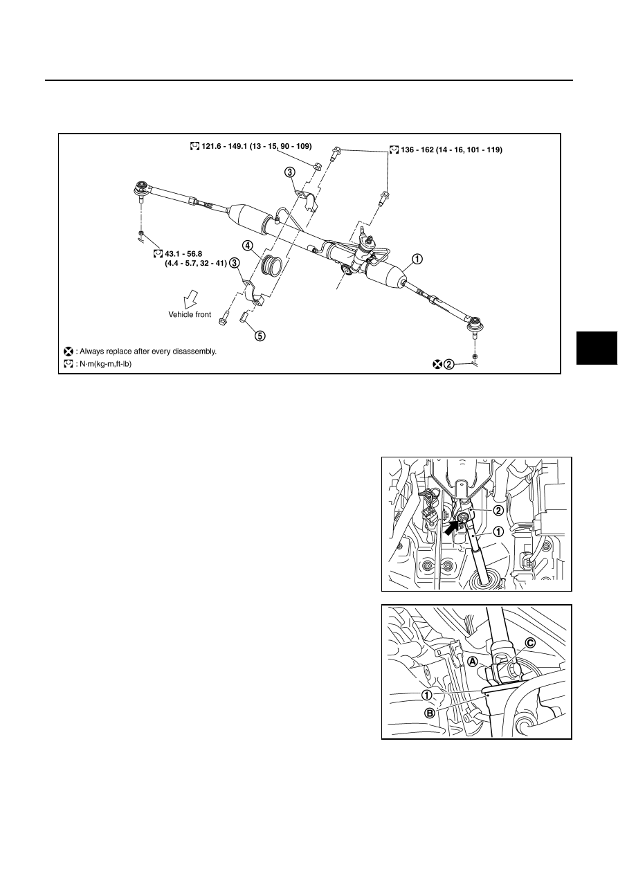
COMPONENT
REMOVAL
2WD
1.
Set vehicle to the straight-ahead position.
2.
Remove lock nut and bolt, then separate lower shaft (1) from
upper joint (2).
3.
Remove tires from vehicle with power tool.
4.
Confirm slit of lower shaft (C) fits with the projection (A) on rear
cover cap (1), furthermore marking position (B) on steering gear
assembly nearly fits with the projection (A) on rear cover cap (1).
5.
Remove cotter pin at steering knuckle, then loosen mounting
nut.
1.
Steering gear assembly
2.
Cotter pin
3.
Rack mounting bracket
4.
Rack mounting insulator
5.
Sleeve
SGIA0486E
SGIA1137E
SGIA1140E