Nissan Murano Z50 (2006 year). Manual - part 164


  Index      Manuals     Nissan Murano Z50 (2006 year) - Service and Repair Manual


Search            copyright infringement  


Content      ..     162      163      164      165     ..


Nissan Murano Z50 (2006 year). Manual - part 164


TURN SIGNAL AND HAZARD WARNING LAMPS

LT-123

C

D

E

F

G

H

I

J

L

M

A

B

LT

Revision: 2006 August

2006 Murano

Terminals and Reference Value for Rear Combination Lamp Control Unit

NKS002SV

45

G/B

Turn signal (left)

ON

Combination switch

Turn left ON

Approx. 6.0 V

46

G/Y

Turn signal 
(right)

ON

Combination switch

Turn right ON

Approx. 6.0 V

52

B

Ground

ON

Approx. 0 V

55

W/B

Battery power 
supply

OFF

Battery voltage

Terminal 

No.

Wire 

color

Signal name

Measuring condition

Reference value

Ignition 

switch

Operation or condition

PKIC6370E

PKIC6370E

Terminal 

No.

Wire 

color

Signal name

Measuring condition

Reference value

Ignition 

switch

Operation or condition

1

R/L

Tail lamp signal

Lighting switch OFF

Approx. 0 V

Lighting switch 1ST

Battery voltage

2

R/G

Stop lamp signal

Brake pedal released 
(stop lamp switch OFF)

Approx. 0 V

Brake pedal depressed 
(stop lamp switch ON)

Battery voltage

3

G/B

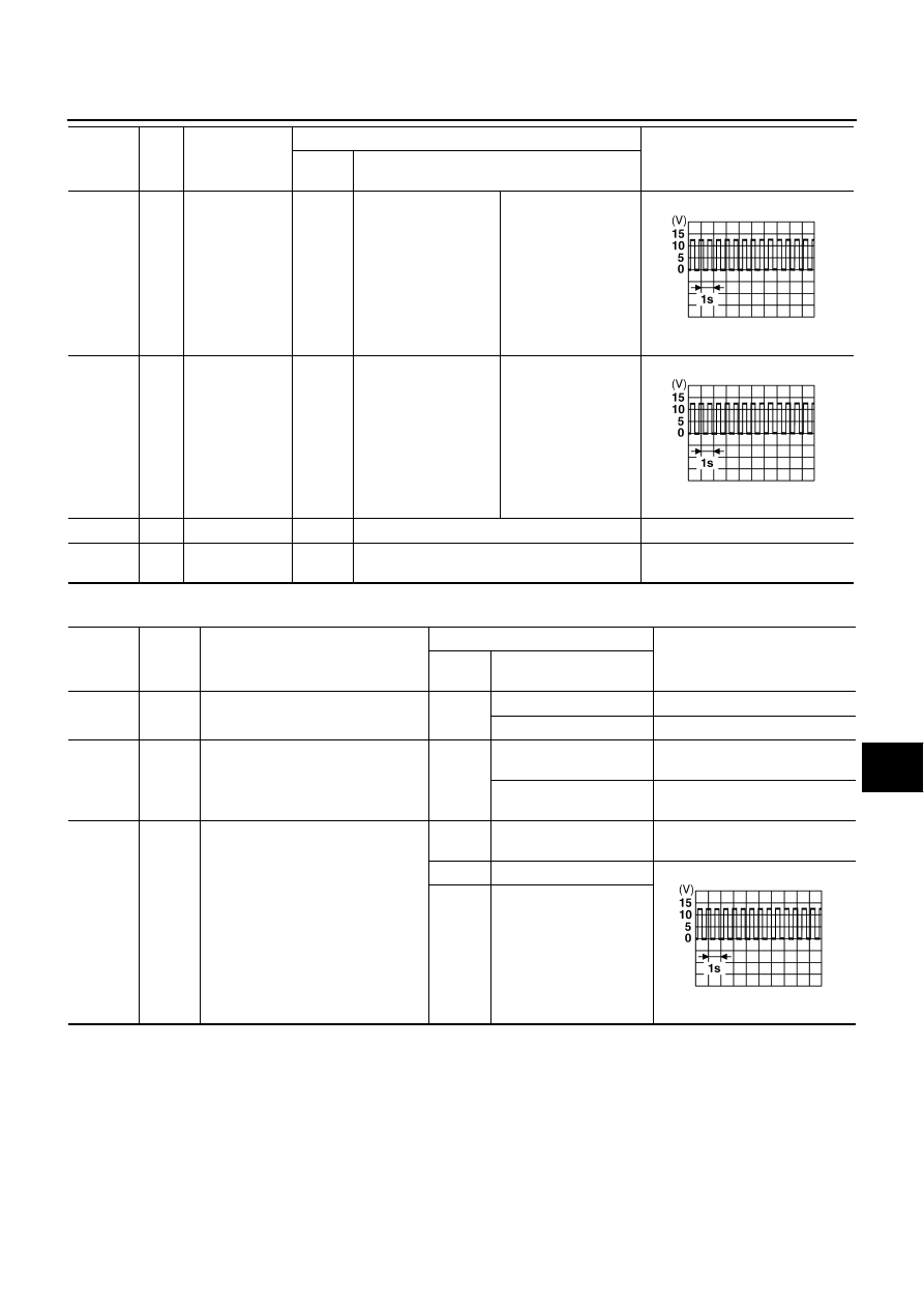
Turn signal lamp LH signal

ON

Turn signal switch OFF, 
hazard switch OFF

Approx. 0 V

ON

Turn signal switch LH

Approx. 6.0 V

Hazard switch ON

PKIC6370E

LT-124

TURN SIGNAL AND HAZARD WARNING LAMPS

Revision: 2006 August

2006 Murano

4

G/Y

Turn signal lamp RH signal

ON

Turn signal switch OFF, 
hazard switch OFF

Approx. 0 V

ON

Turn signal switch RH

Approx. 6.0 V

Hazard switch ON

5

Y

Rear combination lamp drive signal 
(LH)

Lighting switch OFF, 
brake pedal released 
(stop lamp switch OFF), 
turn signal switch OFF, 
hazard switch OFF

Approx. 0 V

Lighting switch 1ST

Approx. 3.0 V

Brake pedal depressed 
(stop lamp switch ON)

Battery voltage

ON

Turn signal switch LH

Approx. 6.0 V

Hazard switch ON

Terminal 

No.

Wire 

color

Signal name

Measuring condition

Reference value

Ignition 

switch

Operation or condition

PKIC6370E

PKIC6371E

PKIC6370E

TURN SIGNAL AND HAZARD WARNING LAMPS

LT-125

C

D

E

F

G

H

I

J

L

M

A

B

LT

Revision: 2006 August

2006 Murano

6

B/Y

LED cut detect signal (LH)

Lighting switch OFF, 
brake pedal released 
(stop lamp switch OFF), 
turn signal switch OFF, 
hazard switch OFF

Approx. 5 V

Lighting switch 1ST

Approx. 3.2 V

Brake pedal depressed 
(stop lamp switch ON)

Approx. 3.6 V

ON

Turn signal switch RH

Approx. 4.2 V

Hazard switch ON

7

W

Rear combination lamp drive signal 
(RH)

Lighting switch OFF, 
brake pedal released 
(stop lamp switch OFF), 
turn signal switch OFF, 
hazard switch OFF

Approx. 0 V

Lighting switch 1ST

Approx. 3.0 V

Brake pedal depressed 
(stop lamp switch ON)

Battery voltage

ON

Turn signal switch RH

Approx. 6.0 V

Hazard switch ON

Terminal 

No.

Wire 

color

Signal name

Measuring condition

Reference value

Ignition 

switch

Operation or condition

PKIC6372E

PKIC6373E

PKIC6371E

PKIC6370E

LT-126

TURN SIGNAL AND HAZARD WARNING LAMPS

Revision: 2006 August

2006 Murano

How to Proceed with Trouble Diagnosis

NKS001PY

1.

Confirm the symptom or customer complaint.

2.

Understand operation description and function description. Refer to 

LT-114, "System Description"

 .

3.

Perform preliminary check. Refer to 

LT-127, "Preliminary Check"

 .

4.

Check symptom and repair or replace the cause of malfunction.

5.

Do turn signal and hazard warning lamps operate normally? If YES, GO TO 6. If NO, GO TO 4.

6.

INSPECTION END

8

B/R

LED cut detect signal (RH)

Lighting switch OFF, 
brake pedal released 
(stop lamp switch OFF), 
turn signal switch OFF, 
hazard switch OFF

Approx. 5 V

Lighting switch 1ST

Approx. 3.2 V

Brake pedal depressed 
(stop lamp switch ON)

Approx. 3.6 V

ON

Turn signal switch RH

Approx. 4.2 V

Hazard switch ON

9

R/Y

Battery power supply

OFF

Battery voltage

11

G/W

Warning output signal

ON

When turn signal lamp 
operates normally

Approx. 6.3 V

Except when turn signal 
lamp operates normally

Approx. 12 V

12

B

Ground

ON

Approx. 0 V

13

BR

Rear combination lamp LH ground

ON

Approx. 0 V

14

B

Rear combination lamp LH ground

ON

Approx. 0 V

16

G

Ignition switch (ON)

ON

Battery voltage

Terminal 

No.

Wire 

color

Signal name

Measuring condition

Reference value

Ignition 

switch

Operation or condition

PKIC6372E

PKIC6373E

PKIC6374E

TURN SIGNAL AND HAZARD WARNING LAMPS

LT-127

C

D

E

F

G

H

I

J

L

M

A

B

LT

Revision: 2006 August

2006 Murano

Preliminary Check

NKS001PZ

CHECK POWER SUPPLY AND GROUND CIRCUIT

1. 

CHECK FUSES AND FUSIBLE LINK

Check for blown fuses and fusible link.

Refer to 

LT-119, "Wiring Diagram — TURN —"

 .

OK or NG

OK

>> GO TO 2.

NG

>> If fuse or fusible link is blown, be sure to eliminate cause of malfunction before installing new fuse

or fusible link. Refer to 

PG-3, "POWER SUPPLY ROUTING CIRCUIT"

 .

2. 

CHECK POWER SUPPLY CIRCUIT 

1.

Turn ignition switch OFF.

2.

Disconnect BCM connector.

3.

Check voltage between BCM harness connector and ground.

OK or NG

OK

>> GO TO 3.

NG

>> Repair harness or connector.

3. 

CHECK GROUND CIRCUIT

Check continuity between BCM harness connector and ground.

OK or NG

OK

>> INSPECTION END

NG

>> Repair harness or connector.

Unit

Power source

Fuse and fusible link No.

BCM

Battery

F

18

Ignition switch ON or START position

1

Ignition switch ACC or ON position

6

(+)

(

)

Ignition switch position

BCM

connector

Terminal

OFF

ACC

ON

M34

11

Ground

Approx. 0 V

Battery 
voltage

Battery 
voltage

38

Approx. 0 V

Approx. 0 V

Battery 
voltage

M35

42

Battery 
voltage

Battery 
voltage

Battery 
voltage

55

Battery 
voltage

Battery 
voltage

Battery 
voltage

PKIB5197E

BCM

connector

Terminal

Ground

Continuity

M35

52

Yes

PKIB5198E

LT-128

TURN SIGNAL AND HAZARD WARNING LAMPS

Revision: 2006 August

2006 Murano

CONSULT-II Functions (BCM)

NKS001Q0

CONSULT-II can display each diagnostic item using the diagnostic test mode shown following.

CONSULT-II BASIC OPERATION

Refer to 

GI-38, "CONSULT-II Start Procedure"

 .

DATA MONITOR
Operation Procedure

1.

Touch “FLASHER” on “SELECT TEST ITEM” screen.

2.

Touch “DATA MONITOR” on “SELECT DIAG MODE” screen.

3.

Touch either “ALL SIGNALS” or “SELECTION FROM MENU” on the “SELECT MONITOR ITEM” screen.

4.

When “SELECTION FROM MENU” is selected, touch items to be monitored. When “ALL SIGNALS” is
selected, all the items will be monitored.

5.

Touch “START”.

6.

Touch “RECORD” while monitoring, then the status of the monitored item can be recorded. To stop
recording, touch “STOP”.

Display Item List

NOTE:
This item is displayed, but cannot be monitored

ACTIVE TEST
Operation Procedure

1.

Touch “FLASHER” on “SELECT TEST ITEM” screen.

2.

Touch “ACTIVE TEST” on “SELECT DIAG MODE” screen.

3.

Touch item to be tested and check operation of the selected item.

4.

During the operation check, touching “OFF” deactivates the operation.

Display Item List

BCM diagnosis part

Diagnosis mode

Description

FLASHER

DATA MONITOR

Displays BCM input data in real time.

ACTIVE TEST

Operation of electrical loads can be checked by sending driving signal to them.

ALL SIGNALS

Monitors all the signals.

SELECTION FROM MENU

Selects items and monitors them.

Monitor item 

Contents

IGN ON SW

“ON/OFF”

Displays “IGN position (ON)/OFF, ACC position (OFF)” judged from the ignition switch signal.

HAZARD SW

“ON/OFF”

Displays “Hazard ON (ON)/Hazard OFF (OFF)” status, determined from hazard switch signal.

TURN SIGNAL R

“ON/OFF”

Displays “Turn right (ON)/Other (OFF)” status, determined from lighting switch signal.

TURN SIGNAL L

“ON/OFF”

Displays “Turn left (ON)/Other (OFF)” status, determined from lighting switch signal.

BRAKE SW

 NOTE

“OFF”

Test item

Description

FLASHER

With a certain operation (OFF, RH, LH), turn signal lamp can be operated.

TURN SIGNAL AND HAZARD WARNING LAMPS

LT-129

C

D

E

F

G

H

I

J

L

M

A

B

LT

Revision: 2006 August

2006 Murano

Turn Signal Lamps Do Not Operate

NKS001Q1

1. 

ACTIVE TEST

With CONSULT-II

1.

Select “FLASHER” during active test. Refer to 

LT-128, "ACTIVE

TEST"

 .

2.

Make sure “FLASHER RIGHT” and “FLASHER LEFT” operates.

Without CONSULT-II

GO TO 2.

OK or NG

OK

>> GO TO 2.

NG

>> GO TO 3.

2. 

CHECK COMBINATION SWITCH INPUT SIGNAL 

With CONSULT-II

Select “BCM” on CONSULT-II. With “FLASHER” data monitor, make
sure “TURN SIGNAL R” and “TURN SIGNAL L” turns ON-OFF
linked with operation of turn signal switch.

Without CONSULT-II

Refer to 

LT-150, "Combination Switch Inspection"

 .

OK or NG

OK

>> Replace BCM. Refer to 

BCS-14, "Removal and Installation of BCM"

 .

NG

>> Check combination switch (lighting switch). Refer to 

LT-150, "Combination Switch Inspection"

 .

Turn signal lamp should operate.

PKIA5276E

When turn signal switch is 
RH position

: TURN SIGNAL R ON

When turn signal switch is 
LH position

: TURN SIGNAL L ON

PKIA7600E

LT-130

TURN SIGNAL AND HAZARD WARNING LAMPS

Revision: 2006 August

2006 Murano

3. 

CHECK TURN SIGNAL CIRCUIT

1.

Turn ignition switch OFF.

2.

Disconnect BCM connector, front combination lamp RH and LH connectors, and rear combination lamp
control unit connector.

3.

Check continuity between BCM harness connector (A) and front
combination lamp harness connector (B).

4.

Check continuity between BCM harness connector (A) and rear
combination lamp control unit harness connector (B).

5.

Check continuity (short circuit) between BCM harness connector
and ground.

OK or NG

OK

>> GO TO 4.

NG

>> Repair harness or connector.

A

B

Continuity

Connector

Terminal

Connector

Terminal

RH

M35

46

RH

E30

2

Yes

LH

45

LH

E17

PKIC6964E

A

B

Continuity

Connector

Terminal

Connector

Terminal

RH

M35

46

B42

4

Yes

LH

45

3

PKIC6965E

BCM connector

Terminal

Ground

Continuity

RH

M35

46

No

LH

45

PKIB5067E

TURN SIGNAL AND HAZARD WARNING LAMPS

LT-131

C

D

E

F

G

H

I

J

L

M

A

B

LT

Revision: 2006 August

2006 Murano

4. 

CHECK TURN SIGNAL OUTPUT VOLTAGE

With CONSULT-II

1.

Connect BCM connector, front combination lamp RH and LH connectors, and rear combination lamp con-
trol unit connector.

2.

Select “FLASHER” during active test. Refer to 

LT-128, "ACTIVE TEST"

 .

3.

When turn signal lamp is operating, check voltage between
BCM harness connector and ground.

Without CONSULT-II

1.

Connect BCM connector, front combination lamp RH and LH connector, and rear combination lamp con-
trol unit connector.

2.

Turn signal switch is turned RH or LH position.

3.

When turn signal lamp is operating, check voltage between
BCM harness connector and ground.

OK or NG

OK

>> Check connector connection bend and loose fit.

NG

>> Replace BCM. Refer to 

BCS-14, "Removal and Installation of BCM"

 .

(+)

(-)

Voltage

BCM connector

Terminal 

RH

M35

46

Ground

Battery voltage

LH

45

PKIC6966E

(+)

(-)

Voltage

BCM connector

Terminal 

RH

M35

46

Ground

LH

45

PKIC6967E

PKIC6370E

LT-132

TURN SIGNAL AND HAZARD WARNING LAMPS

Revision: 2006 August

2006 Murano

Turn Signal Lamps Go ON, But Flash at High Speed (Both Sides)

NKS002SX

NOTE:
Check if LED circuit is normally. Refer to 

LT-116, "LED Cut Detect Function"

 .

1. 

CHECK WARNING OUTPUT SIGNAL

Select “METER A/C AMP” on CONSULT-II. With data monitor to
make sure “RR COMB STATE” turns OK-NG linked with operation of
turn signal switch.

OK or NG

OK

>> Check CAN communication. Refer to 

BCS-13, "CAN Communication Inspection Using CON-

SULT-II (Self-Diagnosis)"

 .

NG

>> GO TO 2.

2. 

CHECK WARNING OUTPUT SIGNAL CIRCUIT

1.

Turn ignition switch OFF.

2.

Disconnect rear combination lamp control unit connector and unified meter and A/C amp. connector.

3.

Check continuity rear combination lampcontrol unit harness con-
nector (A) B42 terminal 11 and unified meter and A/C amp. har-
ness connector (B) M49 terminal 16.

4.

Check continuity (short circuit) between rear combination lamp
control unit harness connector (A) B42 terminal 11 and ground.

OK or NG

OK

>> GO TO 3.

NG

>> Repair harness or connector.

When turn signal switch is 
RH or LH position 

: RR COMB STATE OK

PKIC6968E

11 – 16

: Continuity should exist.

11 – Ground

: Continuity should not exist.

PKIC6971E

TURN SIGNAL AND HAZARD WARNING LAMPS

LT-133

C

D

E

F

G

H

I

J

L

M

A

B

LT

Revision: 2006 August

2006 Murano

3. 

CHECK WARNING OUTPUT SIGNAL

1.

Connect rear combination lamp control unit connector and unified meter and A/C amp. connector.

2.

Hazard switch is ON.

3.

Check voltage between rear combination lamp control unit har-
ness connector B42 terminal 11 and ground.

OK or NG

OK

>> Replace unified meter and A/C amp.. 

NG

>>

If voltage is approx. 0 V, GO TO 4.

If voltage is approx. 12 V, replace rear combination lamp control unit.

4. 

CHECK UNIFIED METER AND A/C AMP. WARNIG OUTPUT SIGNAL POWER SUPPLY

1.

Discnnect rear combination lamp control unit connector.

2.

Check voltage between rear combination lamp control unit har-
ness connector B42 terminal 11 and ground.

OK or NG

OK

>> Replace rear combination lamp control unit.

NG

>> Replace unified meter and A/C amp.. 

11 – Ground

:

PKIC6969E

PKIC6374E

11 – Ground

: Battery voltage.

PKIC6970E

LT-134

TURN SIGNAL AND HAZARD WARNING LAMPS

Revision: 2006 August

2006 Murano

Turn Signal Lamps Go ON, But Flash at High Speed (One Side)

NKS002SZ

NOTE:
Check if LED circuit is normally. Refer to 

LT-116, "LED Cut Detect Function"

 .

1. 

CHECK WARNING OUTPUT SIGNAL

Select “METER A/C AMP” on CONSULT-II. With data monitor to
make sure “RR COMB STATE” turns OK-NG linked with operation of
turn signal switch.

OK or NG

OK

>> GO TO 2.

NG

>> GO TO 4.

2. 

CHECK FRONT TURN SIGNAL LAMP BULB

Check front turn signal lamp bulb standard of front turn signal lamp RH or LH is correct.

OK or NG

OK

>> GO TO 3.

NG

>> Replace turn signal lamp bulb.

When turn signal switch is 
RH or LH position 

: RR COMB STATE OK

PKIC6968E

TURN SIGNAL AND HAZARD WARNING LAMPS

LT-135

C

D

E

F

G

H

I

J

L

M

A

B

LT

Revision: 2006 August

2006 Murano

3. 

CHECK TURN SIGNAL CIRCUIT

1.

Turn ignition switch OFF.

2.

Disconnect BCM connector, front combination lamp RH or LH connectors, and rear conbination lamp con-
trol unit connector.

3.

Check continuity between BCM harness connector (A) and front
combination lamp harness connector (B).

4.

Check continuity between BCM harness connector (A) and rear
combination lamp control unit harness connector (B).

OK or NG

OK

>> Check connector connection bend and loose fit.

NG

>> Repair harness or connector.

4. 

CHECK LED CUT DETECT SIGNAL CIRCUIT

1.

Turn ignition switch OFF.

2.

Disconnect rear combination lamp control unit connector and rear combination lamp RH or LH connec-
tors.

3.

Check continuity rear combination lamp control unit harness
connector (A) and rear combination lamp harness connector (B).

4.

Check continuity (short circuit) between rear combination lamp
control unit (A) harness connector and ground.

OK or NG

OK

>> GO TO 5.

NG

>> Repair harness or connector.

A

B

Continuity

Connector

Terminal

Connector

Terminal

RH

M35

46

RH

E30

2

Yes

LH

45

LH

E17

PKIC6964E

A

B

Continuity

Connector

Terminal

Connector

Terminal

RH

M35

46

B42

4

Yes

LH

45

3

PKIC6965E

A

B

Continuity

Connector

Terminal

Connector

Terminal

B42

8

RH

B29

3

Yes

6

LH

B24

A

Ground

Continuity

Connector

Terminal

RH

B42

8

No

LH

6

PKIC6972E

LT-136

TURN SIGNAL AND HAZARD WARNING LAMPS

Revision: 2006 August

2006 Murano

5. 

CHECK LED CUT DETECT SIGNAL

1.

Turn ignition switch OFF.

2.

Connect rear conbination lamp control unit connector and rear combination lamp RH or LH connectors.

3.

Hazard switch is ON.

4.

Check voltage between rear combination lamp control unit har-
ness connector and ground.

OK or NG

OK

>> Replace rear combination lamp control unit.

NG

>> GO TO 6.

6. 

CHECK REAR COMBINATION LAMP CONTROL UNIT LED CUT DETECT SIGNAL POWER SUPPLY

1.

Disconnect rear combination lamp connector.

2.

Turn ignition switch ON.

3.

Check voltage between rear combination lamp control unit har-
ness connector and ground.

OK or NG

OK

>> Replace rear combination lamp. 

NG

>> Replace rear combination lamp comtrol unit.

(+)

(-)

Voltage

Rear combination 

lamp control unit 

connector

Terminal 

B42

RH

8

Ground

LH

6

PKIC6973E

PKIC6373E

(+)

(-)

Voltage

Rear combination lamp 

control unit connector

Terminal 

RH

B42

8

Ground

Approx. 5 V

LH

6

PKIC6974E

TURN SIGNAL AND HAZARD WARNING LAMPS

LT-137

C

D

E

F

G

H

I

J

L

M

A

B

LT

Revision: 2006 August

2006 Murano

Hazard Warning Lamps Do Not Operate But Turn Signal Lamps Operate

NKS001Q2

1. 

CHECK HAZARD SWITCH INPUT SIGNAL

With CONSULT-II

Select “BCM” on CONSULT-II. With “FLASHER” data monitor to
make sure “HAZARD SW” turns ON-OFF linked with operation of
hazard switch.

Without CONSULT-II

GO TO 2.

OK or NG

OK

>> Replace BCM. Refer to 

BCS-14, "Removal and Installation of BCM"

 .

NG

>> GO TO 2.

2. 

CHECK HAZARD SWITCH CIRCUIT

1.

Turn ignition switch OFF.

2.

Disconnect BCM connector and combination meter connector.

3.

Check continuity BCM harness connector (A) M34 terminal 29
and combination meter harness connector (B) M25 terminal 9.

4.

Check continuity (short circuit) BCM harness connector (A) M34
terminal 29 and ground.

OK or NG

OK

>> GO TO 3.

NG

>> Repair harness or connector.

When hazard switch is ON 
position 

: HAZARD SW ON

PKIA7601E

29 – 9

: Continuity should exist.

29 – Ground

: Continuity should not exist.

PKIC6979E

LT-138

TURN SIGNAL AND HAZARD WARNING LAMPS

Revision: 2006 August

2006 Murano

3. 

CHECK HAZARD SWITCH INPUT SIGNAL

1.

Connect BCM connector and combination meter connector.

2.

Check voltage between BCM harness connector M34 terminal
29 and ground.

OK or NG

OK

>> Replace BCM. Refer to 

BCS-14, "Removal and Installation of BCM"

 .

NG

>>

If voltage is approx. 0 V, replace BCM. Refer to 

BCS-14, "Removal and Installation of BCM"

 .

If voltage is approx. 12 V, GO TO 4.

4. 

CHECK HAZARD SWITCH

1.

Turn ignition switch OFF.

2.

Remove hazard switch. Refer to 

DI-24, "Disassembly and

Assembly of Combination Meter"

 .

3.

Check continuity hazard switch terminals.

OK or NG

OK

>> GO TO 5.

NG

>> Replace hazard switch.

5. 

CHECK HAZARD SWITCH CIRCUIT

1.

Disconnect combination meter connector and hazard switch connector.

2.

Check continuity between hazard switch harness connector and
combination meter harness connector.

OK or NG

OK

>> Replace combination meter.

NG

>> Repair harness or connector.

(+)

(

)

Condition

Voltage

BCM

connector

Terminal

M34

29

Ground

Hazard switch is ON

Approx. 0 V

Hazard switch is OFF

Approx. 12 V

PKIA6354E

Terminal

Condition

Continuity

Hazard switch

1

2

Hazard switch is ON

Yes

Hazard switch is OFF

No

PKIB2171E

Hazard switch

Combination meter

Continuity

Connector

Terminal

Connector

Terminal

M304

1

M302

36

Yes

2

33

PKIB2151E


Content      ..     162      163      164      165     ..