Nissan Murano Z50 (2006 year). Manual - part 160


  Index      Manuals     Nissan Murano Z50 (2006 year) - Service and Repair Manual


Search            copyright infringement  


Content      ..     158      159      160      161     ..


Nissan Murano Z50 (2006 year). Manual - part 160


HEADLAMP -CONVENTIONAL TYPE-

LT-59

C

D

E

F

G

H

I

J

L

M

A

B

LT

Revision: 2006 August

2006 Murano

3. 

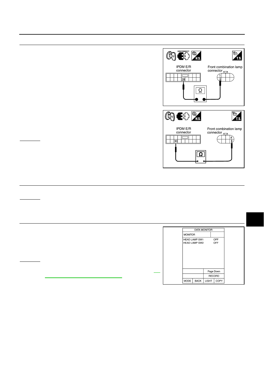
CHECK HEADLAMP CIRCUIT 

1.

Disconnect IPDM E/R connector.

2.

Check continuity between IPDM E/R harness connector E7 ter-
minal 28 and front combination lamp LH harness connector E17
terminal 1.

3.

Check continuity between IPDM E/R harness connector E7 ter-
minal 30 and front combination lamp LH harness connector E17
terminal 4.

OK or NG

OK

>> Replace IPDM E/R.

NG

>> Repair harness or connector.

Headlamps Do Not Turn OFF

NKS001O5

1. 

CHECK HEADLAMP TURN OFF

Make sure that lighting switch is OFF. And make sure headlamps turns off when ignition switch is turned OFF.

OK or NG

OK

>> GO TO 3.

NG

>> GO TO 2.

2. 

CHECK COMBINATION SWITCH INPUT SIGNAL 

Select “BCM” on CONSULT-II. With “HEAD LAMP” data monitor,
make sure “HEAD LAMP SW 1” and “HEAD LAMP SW 2” turn ON-
OFF linked with operation of lighting switch.

OK or NG

OK

>> Replace IPDM E/R.

NG

>> Check combination lamp (lighting switch). Refer to 

LT-

150, "Combination Switch Inspection"

 .

28 – 1

: Continuity should exist.

PKIA6333E

30 – 4

: Continuity should exist.

PKIB2184E

When lighting switch is OFF 
position

: HEAD LAMP SW 1 OFF
: HEAD LAMP SW 2 OFF

PKIA7588E

LT-60

HEADLAMP -CONVENTIONAL TYPE-

Revision: 2006 August

2006 Murano

3. 

CHECKING CAN COMMUNICATIONS BETWEEN BCM AND IPDM E/R

Select “BCM” on CONSULT-II, and perform self-diagnosis for
“BCM”.

Display of self-diagnosis results

NO DTC>> Replace IPDM E/R.
CAN COMM CIRCUIT>>  Refer  to 

BCS-13, "CAN Communication

Inspection Using CONSULT-II (Self-Diagnosis)"

 .

Aiming Adjustment

NKS001O6

PREPARATION BEFORE ADJUSTING

For Details, Refer To the Regulations In Your Own Country.
Before performing aiming adjustment, check the following. 

1.

Keep all tires inflated to correct pressures.

2.

Place vehicle on level ground.

3.

Set that there is no-load in vehicle other than the driver (or equivalent weight placed in driver's position).
Coolant, engine oil filled up to correct level and full fuel tank.

LOW BEAM AND HIGH BEAM

1.

Turn headlamp low beam ON.

2.

Use adjusting screws to perform aiming adjustment.

PKIA7627E

PKIA2515E

HEADLAMP -CONVENTIONAL TYPE-

LT-61

C

D

E

F

G

H

I

J

L

M

A

B

LT

Revision: 2006 August

2006 Murano

ADJUSTMENT USING AN ADJUSTMENT SCREEN (LIGHT/DARK BORDERLINE)

If the vehicle front body has been repaired and/or the headlamp assembly has been replaced, check aiming.
Use the aiming chart shown in the figure.

Basic illumination area for adjustment should be within the range shown on the aiming chart.
Adjust headlamp accordingly.

Bulb Replacement

NKS001O7

HEADLAMP HIGH/LOW BEAM 

1.

Turn lighting switch OFF.

2.

Remove fender protector (front). Refer to 

EI-21, "FENDER PROTECTOR"

   in “EI” section.

3.

Turn plastic cap counterclockwise and unlock it.

4.

Disconnect bulb terminal.

5.

Unlock retaining spring and remove bulb from headlamp.

6.

Installation is the reverse order of removal.

PKIB2152E

Headlamp high/low beam (Halogen)

: 12V - 65/55W (HB5)

LT-62

HEADLAMP -CONVENTIONAL TYPE-

Revision: 2006 August

2006 Murano

PARKING LAMP

1.

Turn lighting switch OFF.

2.

Remove air cleaner case (when replacing LH bulb). Refer to 

EM-16, "AIR CLEANER AND AIR DUCT"

 .

3.

Remove IPDM E/R (when replacing RH bulb). Refer to 

PG-28, "Removal and Installation of IPDM E/R"

 . 

4.

Turn bulb socket counterclockwise and unlock it.

5.

Remove bulb from its socket.

6.

Installation is the reverse order of removal.

FRONT TURN SIGNAL LAMP

1.

Turn lighting switch OFF.

2.

Remove fender protector (front). Refer to 

EI-21, "FENDER PROTECTOR"

 .

3.

Turn bulb socket counterclockwise and unlock it.

4.

Remove bulb from its socket.

5.

Installation is the reverse order of removal.

CAUTION:

After installing bulb, be sure to install plastic cap and bulb socket securely to insure watertight-
ness.

FRONT SIDE MARKER LAMP

1.

Turn lighting switch OFF.

2.

Remove fender protector (front). Refer to 

EI-21, "FENDER PROTECTOR"

 .

3.

Turn bulb socket counterclockwise and unlock it.

4.

Remove bulb from its socket.

5.

Installation is the reverse order of removal.

CAUTION:

After installing bulb, be sure to install plastic cap and socket securely to insure watertightness.

Removal and Installation

NKS001O8

REMOVAL

1.

Remove front bumper. Refer to 

EI-14, "FRONT BUMPER"

 .

2.

Remove headlamp mounting bolts.

3.

Remove plastics bumper bracket, then pull headlamp toward
vehicle front, disconnect connector, and remove headlamp. 

INSTALLATION

Installation is the reverse order of removal.

NOTE:
After installation, perform aiming adjustment. Refer to 

LT-60, "Aiming Adjustment"

 .

Parking lamp

: 12V - 3.8W

Front turn signal lamp 

: 12V - 21W (amber)

Front side marker lamp 

: 12V - 3.8W 

PKIA2519E

Headlamp mounting bolt

: 5.1N·m (0.52 kg-m, 45 in-lb)

HEADLAMP -CONVENTIONAL TYPE-

LT-63

C

D

E

F

G

H

I

J

L

M

A

B

LT

Revision: 2006 August

2006 Murano

Disassembly and Assembly

NKS001O9

DISASSEMBLY

1.

Disconnect the connector to the halogen bulb (high/low).

2.

Turn plastic holder counterclockwise and unlock it.

3.

Disconnect bulb socket. 

4.

Unlock retaining spring, and remove halogen bulb (high/low).

5.

Turn parking lamp bulb socket counterclockwise and unlock it.

6.

Remove parking lamp bulb from its socket.

7.

Turn front turn signal lamp bulb socket counterclockwise and unlock it.

8.

Remove front turn signal lamp bulb from its socket.

9.

Turn front side marker lamp bulb socket counterclockwise and unlock it.

10. Remove front side lamp marker lamp bulb from its socket.

ASSEMBLY

Assembly is the reverse order of disassembly.

CAUTION:

After installing bulb, be sure to install plastic cap and bulb socket securely to insure watertightness.

1.

Side marker lamp bulb

2.

Side marker lamp bulb socket

3.

Halogen bulb connector

4.

Front turn signal lamp bulb

5.

Front turn signal lamp bulb socket

6.

Plastic holder

7.

Halogen bulb

8.

Parking lamp bulb socket

9.

Parking lamp bulb

10. Headlamp housing assembly

PKIA2518E

LT-64

DAYTIME LIGHT SYSTEM

Revision: 2006 August

2006 Murano

DAYTIME LIGHT SYSTEM

PFP:284B2

Component Parts and Harness Connector Location

NKS001OA

System Description

NKS001OB

Daytime light system turns ON daytime light lamps (front fog lamps) while driving. Daytime light lamps are not
turned ON if engine is activated with parking brake ON. Release parking brake to turn on daytime light lamps.
The lamps turn OFF when lighting switch is in the 2ND position or AUTO position (headlamp is ON) and when
lighting switch is in the PASSING position. (Daytime light lamps are not turned off only by parking brake itself.)
A parking brake signal and engine run or stop signal are sent to BCM (body control module) by CAN commu-
nication line, and control daytime light system.

OUTLINE

Power is supplied at all times

to ignition relay located in IPDM E/R (intelligent power distribution module engine room), from battery
direct,

PKIB2158E

DAYTIME LIGHT SYSTEM

LT-65

C

D

E

F

G

H

I

J

L

M

A

B

LT

Revision: 2006 August

2006 Murano

through 15A fuse (No. 88, located in IPDM E/R)

to front fog lamp relay located in IPDM E/R,

through 10A fuse (No. 71, located in IPDM E/R)

to CPU (central processing unit) located in IPDM E/R,

through 15A fuse (No. 78, located in IPDM E/R)

to CPU located in IPDM E/R,

through 50A fusible link (letter F, located in fuse and fusible link block)

to BCM terminal 55,

through 10A fuse [No. 18, located in fuse block (J/B)]

to BCM terminal 42,

through 10A fuse [No. 21, located in fuse block (J/B)]

to combination meter terminal 21.

When the ignition switch is in ON or START position, power is supplied

to ignition relay located in IPDM E/R,

through 10A fuse [No. 1, located in fuse block (J/B)]

to BCM terminal 38,

through 10A fuse [No. 14, located in fuse block (J/B)]

to combination meter terminal 20.

When the ignition switch is in ACC or ON position, power is supplied

through 10A fuse [No. 6, located in fuse block (J/B)]

to BCM terminal 11.

Ground is supplied

to BCM terminal 52

through grounds M14 and M78,

to IPDM E/R terminals 38 and 60

through grounds E13, E26 and E28,

to combination meter terminals 22, 23 and 24

through grounds M14 and M78.

DAYTIME LIGHT OPERATION

Once the parking brake is turned OFF after ignition switch ON, if the lighting switch is turned OFF while engine
running, the BCM sends front fog lamp request signal (ON) through CAN communication.
When receiving front fog lamp request signal (ON), IPDM E/R turns ON front fog lamp relay in IPDM E/R.
IPDM E/R supplies power

through IPDM E/R terminal 37

to front fog lamp LH terminal 1,

through IPDM E/R terminal 36

to front fog lamp RH terminal 1.

Ground is supplied

to front fog lamp RH and LH terminals 2

through grounds E13, E26 and E28.

With power and ground supplied, front fog lamp illuminate.

COMBINATION SWITCH READING FUNCTION

Refer to 

BCS-3, "COMBINATION SWITCH READING FUNCTION"

 .

EXTERIOR LAMP BATTERY SAVER CONTROL

With the combination switch (lighting switch) is in the 2ND position (ON), and the ignition switch is turned from
ON or ACC to OFF, the battery saver control function is activated.
Under this condition, the front fog lamps remain illuminated for 5 minutes, and then the front fog lamps are
turned off.
Exterior lamp battery saver control made can be changed by the function setting of CONSULT-II.

LT-66

DAYTIME LIGHT SYSTEM

Revision: 2006 August

2006 Murano

AUTO LIGHT OPERATION

For auto light operation, refer to 

LT-81, "System Description"

  in “AUTO LIGHT SYSTEM”. 

CAN Communication System Description

NKS001OC

CAN (Controller Area Network) is a serial communication line for real time application. It is an on-vehicle mul-
tiplex communication line with high data communication speed and excellent error detection ability. Many elec-
tronic control units are equipped onto a vehicle, and each control unit shares information and links with other
control units during operation (not independent). In CAN communication, control units are connected with 2
communication lines (CAN H line, CAN L line) allowing a high rate of information transmission with less wiring.
Each control unit transmits/receives data but selectively reads required data only.

CAN Communication Unit

NKS001OD

Refer to 

LAN-32, "CAN Communication Unit"

 .

DAYTIME LIGHT SYSTEM

LT-67

C

D

E

F

G

H

I

J

L

M

A

B

LT

Revision: 2006 August

2006 Murano

Schematic

NKS001OE

TKWB0446E

LT-68

DAYTIME LIGHT SYSTEM

Revision: 2006 August

2006 Murano

Wiring Diagram — DTRL —

NKS001OF

TKWB0447E

DAYTIME LIGHT SYSTEM

LT-69

C

D

E

F

G

H

I

J

L

M

A

B

LT

Revision: 2006 August

2006 Murano

TKWB2558E

LT-70

DAYTIME LIGHT SYSTEM

Revision: 2006 August

2006 Murano

TKWB2559E

DAYTIME LIGHT SYSTEM

LT-71

C

D

E

F

G

H

I

J

L

M

A

B

LT

Revision: 2006 August

2006 Murano

Terminals and Reference Values for BCM

NKS001OG

Terminal 

No.

Wire 

color

Signal name

Measuring condition

Reference value

Ignition 

switch

Operation or condition

2

R

Combination 
switch input 5

ON

Lighting, turn, wiper 
switch
(Wiper intermittent 
dial position 4)

OFF

Approx. 0 V

Lighting switch 2ND

Approx. 2.0 V

3

P/L

Combination 
switch input 4

ON

Lighting, turn, wiper 
switch
(Wiper intermittent 
dial position 4)

OFF

Approx. 0 V

Front fog lamp switch 
(Operate only front fog 
lamp switch)

Approx. 0.8 V

Any of the conditions 
below

Lighting switch 2ND

Lighting switch PASS-
ING
(Operates only PASS-
ING switch)

Approx. 1.0 V

4

R/G

Combination 
switch input 3

ON

Lighting, turn, wiper 
switch
(Wiper intermittent 
dial position 4)

OFF

Approx. 0 V

Any of the conditions 
below

Lighting switch AUTO

Approx. 1.0 V

11

P/B

Ignition switch 
(ACC)

ACC

Battery voltage

PKIB4953J

PKIB4955J

PKIB4959J

PKIB4959J

LT-72

DAYTIME LIGHT SYSTEM

Revision: 2006 August

2006 Murano

32

LG/B

Combination 
switch output 5

ON

Lighting, turn, wiper 
switch
(Wiper intermittent 
dial position 4)

OFF

Approx. 7.2 V

Front fog lamp switch 
(Operates only front fog 
lamp switch)

Approx. 1.0 V

33

G/Y

Combination 
switch output 4

ON

Lighting, turn, wiper 
switch
(Wiper intermittent 
dial position 4)

OFF

Approx. 7.2 V

Lighting switch AUTO

Approx. 1.2 V

34

LG/R

Combination 
switch output 3

ON

Lighting, turn, wiper 
switch
(Wiper intermittent 
dial position 4)

OFF

Approx. 7.2 V

Lighting switch 2ND

Approx. 1.2 V

Terminal 

No.

Wire 

color

Signal name

Measuring condition

Reference value

Ignition 

switch

Operation or condition

PKIB4960J

PKIB4956J

PKIB4960J

PKIB4958J

PKIB4960J

PKIB4958J

DAYTIME LIGHT SYSTEM

LT-73

C

D

E

F

G

H

I

J

L

M

A

B

LT

Revision: 2006 August

2006 Murano

Terminals and Reference Values for IPDM E/R

NKS001OH

How to Proceed with Trouble Diagnosis

NKS001OI

1.

Confirm the symptom or customer complaint.

2.

Understand operation description and function description. Refer to 

LT-64, "System Description"

 .

3.

Perform the Preliminary Check. Refer to 

LT-74, "Preliminary Check"

 .

4.

Check symptom and repair or replace the cause of malfunction.

5.

Does the front fog lamp operate normally? If YES, GO TO 6. If NO, GO TO 4.

6.

INSPECTION END

35

G/B

Combination 
switch output 2

ON

Lighting, turn, wiper 
switch
(Wiper intermittent 
dial position 4)

OFF

Approx. 7.2 V

Any of the conditions 
below

Lighting switch 2ND

Lighting switch PASS-
ING
(Operates only PASS-
ING switch)

Approx. 1.2 V

38

R

Ignition switch 
(ON) 

ON

Battery voltage

39

L

CAN 


H

40

Y

CAN 


L

42

GR

Battery power 
supply

OFF

Battery voltage

52

B

Ground

ON

Approx. 0 V

55

W/B

Battery power 
supply

OFF

Battery voltage

Terminal 

No.

Wire 

color

Signal name

Measuring condition

Reference value

Ignition 

switch

Operation or condition

PKIB4960J

PKIB4958J

Terminal No.

Wire color

Signal name

Measuring condition

Reference value

Ignition 

switch

Operation or condition

36

G/W

Front fog lamp (RH) 

ON

Front fog lamp switch
(when lighting switch is 1ST position)

OFF

Approx. 0 V

ON

Battery voltage

37

W/R

Front fog lamp (LH)

ON

Front fog lamp switch
(when lighting switch is 1ST position)

OFF

Approx. 0 V

ON

Battery voltage

38 B

Ground

ON

Approx. 

V

48

L

CAN 


H

49

Y

CAN 


L

60

B

Ground

ON

Approx. 0 V

LT-74

DAYTIME LIGHT SYSTEM

Revision: 2006 August

2006 Murano

Preliminary Check

NKS001OJ

CHECK POWER SUPPLY AND GROUND CIRCUIT

1. 

CHECK FUSES AND FUSIBLE LINK

Check for blown fuses and fusible link.

Refer to 

LT-68, "Wiring Diagram — DTRL —"

 .

OK or NG

OK

>> GO TO 2.

NG

>> If fuse or fusible link is blown, be sure to eliminate cause of malfunction before installing new fuse

or fusible link. Refer to 

PG-3, "POWER SUPPLY ROUTING CIRCUIT"

 .

2. 

CHECK POWER SUPPLY CIRCUIT 

1.

Turn ignition switch OFF.

2.

Disconnect BCM connector.

3.

Check voltage between BCM harness connector and ground.

OK or NG

OK

>> GO TO 3.

NG

>> Repair harness or connector.

3. 

CHECK GROUND CIRCUIT

Check continuity between BCM harness connector and ground.

OK or NG

OK

>> INSPECTION END

NG

>> Repair harness or connector.

Unit

Power source

Fuse and fusible link No.

BCM

Battery

F

18

Ignition switch ON or START position

1

Ignition switch ACC or ON position

6

IPDM E/R

Battery

88

(+)

(

)

Ignition switch position

BCM con-

nector

Terminal

OFF

ACC

ON

M34

11

Ground

Approx. 0 V

Battery 
voltage

Battery 
voltage

38

Approx. 0 V

Approx. 0 V

Battery 
voltage

M35

42

Battery 
voltage

Battery 
voltage

Battery 
voltage

55

Battery 
voltage

Battery 
voltage

Battery 
voltage

PKIB5197E

BCM connec-

tor

Terminal

Ground

Continuity

M35

52

Yes

PKIB5198E


Content      ..     158      159      160      161     ..