Index Manuals Nissan Murano Z50 (2006 year) - Service and Repair Manual
Search copyright infringement
Content .. 137 138 139 140 ..
Nissan Murano Z50 (2006 year). Manual - part 139
GW-24
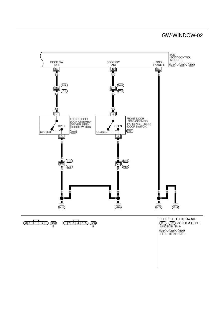
POWER WINDOW SYSTEM
Revision: 2006 August
2006 Murano
TIWB0796E