Nissan Murano Z50 (2006 year). Manual - part 136
 

  Index      Manuals     Nissan Murano Z50 (2006 year) - Service and Repair Manual


Search            copyright infringement  


Content      ..     134      135      136      137     ..


Nissan Murano Z50 (2006 year). Manual - part 136


GI-30

SERVICE INFORMATION FOR ELECTRICAL INCIDENT

Revision: 2006 August

2006 Murano

Cold or Hot Start Up 

On some occasions an electrical incident may occur only when the car is started cold, or it may occur when
the car is restarted hot shortly after being turned off. In these cases you may have to keep the car overnight to
make a proper diagnosis.

CIRCUIT INSPECTION 
Introduction 

In general, testing electrical circuits is an easy task if it is approached in a logical and organized method.
Before beginning it is important to have all available information on the system to be tested. Also, get a thor-
ough understanding of system operation. Then you will be able to use the appropriate equipment and follow
the correct test procedure.
You may have to simulate vehicle vibrations while testing electrical components. Gently shake the wiring har-
ness or electrical component to do this.

NOTE:
Refer to “How to Check Terminal”  to probe or check terminal.

Testing for “Opens” in the Circuit 

Before you begin to diagnose and test the system, you should rough sketch a schematic of the system. This
will help you to logically walk through the diagnosis process. Drawing the sketch will also reinforce your work-
ing knowledge of the system.

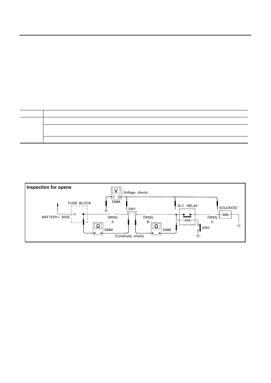
CONTINUITY CHECK METHOD
The continuity check is used to find an open in the circuit. The digital multimeter (DMM) set on the resistance
function will indicate an open circuit as over limit (no beep tone or no ohms symbol). Make sure to always start
with the DMM at the highest resistance level. 
To help in understanding the diagnosis of open circuits, please refer to the previous schematic.

Disconnect the battery negative cable.

Start at one end of the circuit and work your way to the other end. (At the fuse block in this example)

Connect one probe of the DMM to the fuse block terminal on the load side.

Connect the other probe to the fuse block (power) side of SW1. Little or no resistance will indicate that
portion of the circuit has good continuity. If there were an open in the circuit, the DMM would indicate an
over limit or infinite resistance condition. (point A)

Connect the probes between SW1 and the relay. Little or no resistance will indicate that portion of the cir-
cuit has good continuity. If there were an open in the circuit, the DMM would indicate an over limit or infi-
nite resistance condition. (point B)

Connect the probes between the relay and the solenoid. Little or no resistance will indicate that portion of
the circuit has good continuity. If there were an open in the circuit, the DMM would indicate an over limit or
infinite resistance condition. (point C)

Any circuit can be diagnosed using the approach in the previous example.

OPEN

A circuit is open when there is no continuity through a section of the circuit.

SHORT

There are two types of shorts.

SHORT CIRCUIT

When a circuit contacts another circuit and causes the normal resistance to 
change.

SHORT TO GROUND

When a circuit contacts a ground source and grounds the circuit.

SGI846-A

SERVICE INFORMATION FOR ELECTRICAL INCIDENT

GI-31

C

D

E

F

G

H

I

J

K

L

M

B

GI

Revision: 2006 August

2006 Murano

VOLTAGE CHECK METHOD
To help in understanding the diagnosis of open circuits please refer to the previous schematic.
In any powered circuit, an open can be found by methodically checking the system for the presence of voltage.
This is done by switching the DMM to the voltage function.

Connect one probe of the DMM to a known good ground.

Begin probing at one end of the circuit and work your way to the other end.

With SW1 open, probe at SW1 to check for voltage.
voltage; open is further down the circuit than SW1.
no voltage; open is between fuse block and SW1 (point A).

Close SW1 and probe at relay.
voltage; open is further down the circuit than the relay.
no voltage; open is between SW1 and relay (point B).

Close the relay and probe at the solenoid.
voltage; open is further down the circuit than the solenoid.
no voltage; open is between relay and solenoid (point C).

Any powered circuit can be diagnosed using the approach in the previous example.

Testing for “Shorts” in the Circuit 

To simplify the discussion of shorts in the system, please refer to the following schematic.

RESISTANCE CHECK METHOD

Disconnect the battery negative cable and remove the blown fuse.

Disconnect all loads (SW1 open, relay disconnected and solenoid disconnected) powered through the
fuse.

Connect one probe of the DMM to the load side of the fuse terminal. Connect the other probe to a known
good ground.

With SW1 open, check for continuity.
continuity; short is between fuse terminal and SW1 (point A).
no continuity; short is further down the circuit than SW1.

Close SW1 and disconnect the relay. Put probes at the load side of fuse terminal and a known good
ground. Then, check for continuity.
continuity; short is between SW1 and the relay (point B).
no continuity; short is further down the circuit than the relay.

Close SW1 and jump the relay contacts with jumper wire. Put probes at the load side of fuse terminal and
a known good ground. Then, check for continuity.
continuity; short is between relay and solenoid (point C).
no continuity; check solenoid, retrace steps.

VOLTAGE CHECK METHOD

Remove the blown fuse and disconnect all loads (i.e. SW1 open, relay disconnected and solenoid discon-
nected) powered through the fuse.

Turn the ignition key to the ON or START position. Verify battery voltage at the battery + side of the fuse
terminal (one lead on the battery + terminal side of the fuse block and one lead on a known good ground).

With SW1 open and the DMM leads across both fuse terminals, check for voltage.
voltage; short is between fuse block and SW1 (point A).

SGI847-A

GI-32

SERVICE INFORMATION FOR ELECTRICAL INCIDENT

Revision: 2006 August

2006 Murano

no voltage; short is further down the circuit than SW1.

With SW1 closed, relay and solenoid disconnected and the DMM leads across both fuse terminals, check
for voltage.
voltage; short is between SW1 and the relay (point B).
no voltage; short is further down the circuit than the relay.

With SW1 closed, relay contacts jumped with fused jumper wire check for voltage.
voltage; short is down the circuit of the relay or between the relay and the disconnected solenoid (point C).
no voltage; retrace steps and check power to fuse block.

Ground Inspection 

Ground connections are very important to the proper operation of electrical and electronic circuits. Ground
connections are often exposed to moisture, dirt and other corrosive elements. The corrosion (rust) can
become an unwanted resistance. This unwanted resistance can change the way a circuit works.
Electronically controlled circuits are very sensitive to proper grounding. A loose or corroded ground can drasti-
cally affect an electronically controlled circuit. A poor or corroded ground can easily affect the circuit. Even
when the ground connection looks clean, there can be a thin film of rust on the surface.
When inspecting a ground connection follow these rules:

Remove the ground bolt or screw.

Inspect all mating surfaces for tarnish, dirt, rust, etc.

Clean as required to assure good contact.

Reinstall bolt or screw securely.

Inspect for “add-on” accessories which may be interfering with the ground circuit.

If several wires are crimped into one ground eyelet terminal, check for proper crimps. Make sure all of the
wires are clean, securely fastened and providing a good ground path. If multiple wires are cased in one
eyelet make sure no ground wires have excess wire insulation.

For detailed ground distribution information, refer to “Ground Distribution” in PG section.

Voltage Drop Tests 

Voltage drop tests are often used to find components or circuits which have excessive resistance. A voltage
drop in a circuit is caused by a resistance when the circuit is in operation.
Check the wire in the illustration. When measuring resistance with DMM, contact by a single strand of wire will
give reading of 0 ohms. This would indicate a good circuit. When the circuit operates, this single strand of wire
is not able to carry the current. The single strand will have a high resistance to the current. This will be picked
up as a slight voltage drop. 
Unwanted resistance can be caused by many situations as follows:

Undersized wiring (single strand example)

Corrosion on switch contacts

Loose wire connections or splices.

SGI853

SERVICE INFORMATION FOR ELECTRICAL INCIDENT

GI-33

C

D

E

F

G

H

I

J

K

L

M

B

GI

Revision: 2006 August

2006 Murano

If repairs are needed always use wire that is of the same or larger gauge.

MEASURING VOLTAGE DROP  —  ACCUMULATED METHOD

Connect the DMM across the connector or part of the circuit you want to check. The positive lead of the
DMM should be closer to power and the negative lead closer to ground.

Operate the circuit.

The DMM will indicate how many volts are being used to “push” current through that part of the circuit.

Note in the illustration that there is an excessive 4.1 volt drop between the battery and the bulb.

MEASURING VOLTAGE DROP  —  STEP-BY-STEP
The step-by-step method is most useful for isolating excessive drops in low voltage systems (such as those in
“Computer Controlled Systems”).
Circuits in the “Computer Controlled System” operate on very low amperage.
The (Computer Controlled) system operations can be adversely affected by any variation in resistance in the
system. Such resistance variation may be caused by poor connection, improper installation, improper wire
gauge or corrosion.
The step by step voltage drop test can identify a component or wire with too much resistance.

SGI974

SAIA0258E

GI-34

SERVICE INFORMATION FOR ELECTRICAL INCIDENT

Revision: 2006 August

2006 Murano

Control Unit Circuit Test 

System Description:When the switch is ON, the control unit lights up the lamp.

INPUT-OUTPUT VOLTAGE CHART

The voltage value is based on the body ground.
*:If high resistance exists in the switch side circuit (caused by a single strand), terminal 1 does not detect battery voltage. Control unit
does not detect the switch is ON even if the switch does not turn ON. Therefore, the control unit does not supply power to light up the
lamp.

INPUT-OUTPUT VOLTAGE CHART

The voltage value is based on the body ground.
*:If high resistance exists in the switch side circuit (caused by a single strand), terminal 2 does not detect approx. 0V. Control unit does
not detect the switch is ON even if the switch does not turn ON. Therefore, the control unit does not control ground to light up the lamp.

MGI034A

Pin 

No.

Item

Condition

Voltage

value [V]

In case of high resistance such as single strand [V] *

1

Switch

Switch ON

Battery voltage

Lower than battery voltage Approx. 8 (Example)

Switch OFF

Approx. 0

Approx. 0

2

Lamp

Switch ON

Battery voltage

Approx. 0 (Inoperative lamp)

Switch OFF

Approx. 0

Approx. 0

MGI035A

Pin 

No.

Item

Condition

Voltage

value [V]

In case of high resistance such as single strand [V] *

1

Lamp

Switch ON

Approx. 0

Battery voltage (Inoperative lamp)

Switch OFF

Battery voltage

Battery voltage

2

Switch

Switch ON

Approx. 0

Higher than 0 Approx. 4 (Example)

Switch OFF

Approx. 5

Approx. 5

SERVICE INFORMATION FOR ELECTRICAL INCIDENT

GI-35

C

D

E

F

G

H

I

J

K

L

M

B

GI

Revision: 2006 August

2006 Murano

Control Units and Electrical Parts

NAS00055

PRECAUTIONS

Never reverse polarity of battery terminals.

Install only parts specified for a vehicle.

Before replacing the control unit, check the input and output and functions of the component parts. 

Do not apply excessive force when disconnecting a connector.

For removal of the lever type connector, pull the lever up to the
direction pointed to by the arrow A in the figure, and then
remove the connector. 

For installation of the lever type connector, pull down the lever to
the direction pointed by the arrow B in the figure, and then push
the connector until a clicking noise is heard.

Do not apply  excessive shock to the control unit by dropping or
hitting it.

Be careful to prevent condensation in the control unit due to
rapid temperature changes and do not let water or rain get on it.
If water is found in the control unit, dry it fully and then install it in
the vehicle.

Be careful not to let oil to get on the control unit connector.

Avoid cleaning the control unit with volatile oil.

Do not disassemble the control unit, and do not remove the
upper and lower covers.

SAIA0253E

SAIA0254E

SAIA0255E

GI-36

SERVICE INFORMATION FOR ELECTRICAL INCIDENT

Revision: 2006 August

2006 Murano

When using a DMM, be careful not to let test probes get close to
each other to prevent the power transistor in the control unit
from damaging battery voltage because of short circuiting.

When checking input and output signals of the control unit, use
the specified check adapter.

SEF348N

CONSULT-II CHECKING SYSTEM

GI-37

C

D

E

F

G

H

I

J

K

L

M

B

GI

Revision: 2006 August

2006 Murano

CONSULT-II CHECKING SYSTEM

PFP:00000

Description

NAS00056

CONSULT-II is a hand-held type tester.  When it is connected with a diagnostic connector equipped on the
vehicle side, it will communicate with the control unit equipped in the vehicle and then enable various
kinds of diagnostic tests.

Refer to “CONSULT-II Software Operation Manual” for more information.

Function and System Application 

NAS00057

x: Applicable

*: This item is indicated, but it is what it does not use.

Diagnostic test 

mode

Function

ENG

INE

TRANSM

ISSION

AL

L

 MO

DE A

W

D/ 

4

W

D

AI

R BAG

METER A/C 

AMP

BC

M

IPDM

 E/R

AUT

O

 DRIVE 

POS.

ABS

AB

S (

In

c

lu

di

ng 

VD

C

)

AIR PRESSURE 

M

O

NIT

O

R

NVI

S

 (N

A

T

S

)

RE

AR

VIEW

 CAM

E

RA

INTEL

L

IGENT KEY

Work support

This mode enables a technician to adjust some devices 
faster and more accurately by following the indications 
on CONSULT-II.

x

x

-

-

-

x

-

x

-

x

x

-

x

x

Self-diagnostic 
results

Self-diagnostic results can be read and erased quickly.

x

x

x

x

x

x

x

x

x

x

x

x

-

x

Trouble diagnos-
tic record

Current self-diagnostic results and all trouble diagnostic 
records previously stored can be read.

-

-

-

x

-

-

-

-

-

-

-

-

-

-

Data monitor

Input/Output data in the ECU can be read.

x

x

x

-

x

x

x

x

x

x

x

-

x

x

CAN diagnosis 
support monitor

The condition of CAN communication line can be indi-
cated.

x

x

x

-

x

x

x

x

x

x

-

-

-

x

Active test

Diagnostic Test Mode in which CONSULT-II drives 
some actuators apart from the ECUs and also shifts 
some parameters in a specified range.

x

-

x

-

-

x

x

x

x

x

x

-

-

x

DTC & SRT con-
firmation

The results of SRT (System Readiness Test) and the 
self-diagnosis status/result can be confirmed.

x

-

-

-

-

-

-

-

-

-

-

-

-

-

ECU (ECM/TCM)  
part number

ECU (ECM/TCM) part number can be read.

x

x

x

-

-

x

-

x

x

x

-

-

x

x

ECU discrimi-
nated No.

Classification number of a replacement ECU can be 
read to prevent an incorrect ECU from being installed.

-

-

-

x

-

-

-

-

-

-

-

-

-

-

Function test

This mode can show results of self-diagnosis of ECU 
with either “OK” or “NG”. For engines, more practical 
tests regarding sensors/switches and/or actuators are 
available.

x

x

-

x

-

-

-

-

x

x

-

-

-

-

Control unit ini-
tialization

All registered ignition key IDs in NATS components can 
be initialized and new IDs can be registered.

-

-

-

-

-

-

-

-

-

-

-

x

-

-

CALIB data

Characteristic information for TCM and CVT assembly 
can be read. Do not use, but displayed.

-

x

-

-

-

-

-

-

-

-

-

-

-

-

Configuration *

-

-

-

-

-

x

-

-

-

-

-

-

-

-

GI-38

CONSULT-II CHECKING SYSTEM

Revision: 2006 August

2006 Murano

Nickel Metal Hydride Battery Replacement 

NAS00058

CONSULT-II contains a nickel metal hydride battery. When replacing the battery obey the following:

WARNING:

Replace the nickel metal hydride battery with Genuine CONSULT-II battery only. Use of another bat-
tery may present a risk of fire or explosion. The battery may present a fire or chemical burn hazard if
mistreated. Do not recharge, disassemble or dispose of in fire.
Keep the battery out of reach of children and discard used battery conforming to the local regulations.

Checking Equipment 

NAS00059

When ordering the following equipment, contact your NISSAN/INFINITI distributor.

CAUTION:

If CONSULT-II is used with no connection of CONSULT-II CONVERTER, malfunctions might be
detected in self-diagnosis depending on control unit which carry out CAN communication. 

If CONSULT-II CONVERTER is not connected with CONSULT-II, vehicle occur the “FAIL SAFE
MODE” which is “LIGHT UP the HEAD LIGHT” and/or “COOLING FAN ROTATING” when CON-
SULT-II is started. 

Previous CONSULT-II “I” and “Y” DLC-I and DLC-II cables should NOT be used anymore because
their DDL connector pins can be damaged during cable swapping.

NOTE:

The CONSULT-II must be used in conjunction with a program card.
CONSULT-II does not require loading (Initialization) procedure.

Be sure the CONSULT-II is turned off before installing or removing a program card.

CONSULT-II Start Procedure

NAS0005A

NOTE:
Turning ignition switch off when performing CAN diagnosis could cause CAN memory to be erased.

1.

Connect CONSULT-II and CONSULT-II CONVERTER to the
data link connector.

Tool name

Description

NISSAN CONSULT-II

1. CONSULT-II unit (Tester internal soft: Resident 

version 3.3.0) and accessories

2. Program card UED05B and AEN04A-1 (For 

NATS)

3. CONSULT-II CONVERTER

4. “CONSULT-II Pigtail” Cable

SAIA0363E

PAIA0070E

CONSULT-II CHECKING SYSTEM

GI-39

C

D

E

F

G

H

I

J

K

L

M

B

GI

Revision: 2006 August

2006 Murano

2.

If necessary, turn on the ignition switch.

3.

Touch “START (NISSAN BASED VHCL)” or System Shortcut
key (eg: ENGINE) on the screen.

4.

Touch necessary system on  "SELECT SYSTEM" screen.
If necessary system is not indicated, check power supply and
ground of system control unit. If it is normal, refer to 

GI-39,

"CONSULT-II Data Link Connector (DLC) Circuit"

 .

5.

Select the desired part to be diagnosed on the "SELECT DIAG
MODE" screen.

CONSULT-II Data Link Connector (DLC) Circuit

NAS0005B

INSPECTION PROCEDURE

If the CONSULT-II cannot diagnose the system properly, check the following items.

NOTE:
The DDL1 and DDL2 circuits from DLC pins 12, 13, 14 and 15 may be connected to more than one system. A
short in a DDL circuit connected to a control unit in one system may affect CONSULT-II access to other sys-
tems.

SAIA0450E

BCIA0030E

BCIA0031E

Symptom

Check item

CONSULT-II cannot access 
any system.

CONSULT-II DLC power supply circuit (Terminal 8) and ground circuit (Terminal 4) (For detailed 
circuit, refer to “MIL & Data Link Connectors Wiring Diagram” in EC section.)

CONSULT-II DLC cable and CONSULT-II CONVERTER

CONSULT-II cannot access 
individual system. (Other sys-
tems can be accessed.)

CONSULT-II program card (Check the appropriate CONSULT-II program card for the system. 
Refer to "Checking Equipment".)

Power supply and ground circuit for the control unit of the system (For detailed circuit, refer to wir-
ing diagram for each system.)

Open or short circuit between the system and CONSULT-II DLC (For detailed circuit, refer to wiring 
diagram for each system.)

Open or short circuit CAN communication line. Refer to 

LAN-3, "Precautions When Using CON-

SULT-II"

 .

GI-40

CONSULT-II CHECKING SYSTEM

Revision: 2006 August

2006 Murano

CIRCUIT DIAGRAM

TAWB0010E

LIFTING POINT

GI-41

C

D

E

F

G

H

I

J

K

L

M

B

GI

Revision: 2006 August

2006 Murano

LIFTING POINT

PFP:00000

Commercial Service Tools 

NAS0005C

CAUTION:

Every time the vehicle is lifted up,  maintain the complete vehicle curb condition.

Since the vehicle's center of gravity changes when removing main parts on the front side (engine,
transmission, suspension etc.), support a jack up point on the rear side garage jack with a mission
jack or  equivalent. 

Since the vehicle's center of gravity changes when removing main parts on the rear side (rear axle,
suspension, etc.), support a jack up point on the front side garage jack with a mission jack or
equivalent. 

Be careful not to smash or do not do anything that would affect piping parts.

Garage Jack and Safety Stand 

NAS0005D

WARNING:

Park the vehicle on a level surface when using the jack. Make sure to avoid damaging pipes,
tubes, etc. under the vehicle.

Never get under the vehicle while it is supported only by the jack. Always use safety stands when
you have to get under the vehicle.

Tool name

Description

Board on attachment

Safety stand attachment

S-NT001

S-NT002

GI-42

LIFTING POINT

Revision: 2006 August

2006 Murano

Place wheel chocks at both front and back of the wheels on the ground.

CAUTION:

There is canister just behind Garage jack point rear. Jack up be carefully.

2-Pole Lift 

NAS0005E

WARNING:

When lifting the vehicle, open the lift arms as wide as possible and ensure that the front and rear of
the vehicle are well balanced.
When setting the lift arm, do not allow the arm to contact the brake tubes, brake cable, fuel lines and
sill spoiler.

PIIB7444E

PAIA0084E

LIFTING POINT

GI-43

C

D

E

F

G

H

I

J

K

L

M

B

GI

Revision: 2006 August

2006 Murano

Board-On Lift 

NAS0005F

CAUTION:

Make sure vehicle is empty when lifting.

The board-on lift attachment set at front end of vehicle
should be set on the front of the sill under the front door
opening.

Position attachments at front and rear ends of board-on lift.

PIIB7445E

GI-44

TOW TRUCK TOWING

Revision: 2006 August

2006 Murano

TOW TRUCK TOWING

PFP:00000

Tow Truck Towing

NAS0005G

CAUTION:

All applicable state or Provincial (in Canada) laws and local laws regarding the towing operation
must be obeyed.

It is necessary to use proper towing equipment to avoid possible damage to the vehicle during
towing operation. Towing is in accordance with Towing Procedure Manual at dealer.

Always attach safety chains before towing.

When towing, make sure that the transmission, steering system and power train are in good order.
If any unit is damaged, dollies must be used.

Never tow an CVT model from the rear (that is backward) with four wheels on the ground. This may
cause serious and expensive damage to the transmission.

2WD MODELS

NISSAN recommends that vehicle be towed with the driving (front) wheels off the ground or that a dolly be
used as illustrated.

CAUTION:

Never tow CVT models with the front wheels on the ground or four wheels on the ground (forward
or backward) as this may cause serious and expensive damage to the transmission.
If it is necessary to tow the vehicle with the rear wheels raised, always use towing dollies under
the front wheels. 

When towing CVT models with the front wheels on towing dollies:

Turn the ignition key to the OFF position, and secure the steering wheel in a straight ahead posi-
tion with a rope or similar device.
Never secure the steering wheel by turning the ignition key to the LOCK position. This may dam-
age the steering lock mechanism.

Move the selector lever to the N (Neutral) position.

PAIA0090E

TOW TRUCK TOWING

GI-45

C

D

E

F

G

H

I

J

K

L

M

B

GI

Revision: 2006 August

2006 Murano

When towing two wheel drive CVT model with the rear wheels on the ground (if you do not use
towing dollies): Always release the parking brake. 

AWD MODELS

NISSAN recommends that a dolly be used as illustrated when towing AWD models.

CAUTION:

Never tow CVT AWD models with any of the wheels on the ground as this may cause serious and
expensive damage to the drive train.

Vehicle Recovery (Freeing a Stuck Vehicle) 

NAS0005H

Tow chains or cables must be attached only to the vehicle recov-
ery hooks or main structural members of the vehicle. Otherwise,
the vehicle body will be damaged.

Pulling devices should be routed so they do not touch any part
of the suspension, steering, brake or cooling systems.

Always pull the cable straight out from the front or rear of the
vehicle. Never pull the vehicle at an angle.

Pull devices such as ropes or canvas straps are not recom-
mended for use in vehicle towing or recovery.

Use the hook as illustrated only, not other parts of the vehicle.
Otherwise, the vehicle body will be damaged.

Use the hook as illustrated only to free a vehicle stuck in sand,
snow, mud, etc. Never tow the vehicle for a long distance using
only the towing hook.

The hook is under tremendous force when used to free a stuck
vehicle. 

Stand clear of a stuck vehicle.

FRONT

1.

Remove the hook cover from the bumper using a suitable tool.

2.

Securely install the hook. (Towing hook is stored with jacking tools.)

Make sure that the hook is properly secured in the stored place after use.

PAIA0091E

PAIA0092E


Content      ..     134      135      136      137     ..