Nissan Murano Z50 (2006 year). Manual - part 130
SERVICE DATA AND SPECIFICATIONS (SDS)
EM-149
C
D
E
F
G
H
I
J
K
L
M
A
EM
Revision: 2006 August
2006 Murano
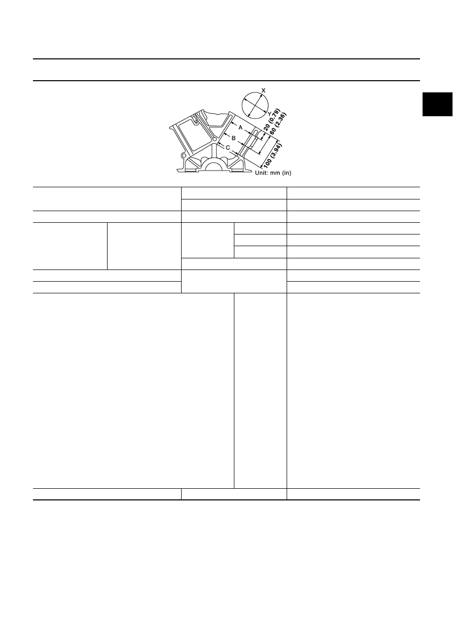
CYLINDER BLOCK
Unit: mm (in)
Surface flatness
Standard
Less than 0.03 (0.0012)
Limit
0.1 (0.004)
Main bearing housing inner diameter
Standard
63.993 - 64.017 (2.5194 - 2.5203)
Cylinder bore
Inner diameter
Standard
Grade No. 1
95.500 - 95.510 (3.7598 - 3.7602)
Grade No. 2
95.510 - 95.520 (3.7602 - 3.7606)
Grade No. 3
95.520 - 95.530 (3.7606 - 3.7610)
Wear limit
0.2 (0.008)
Out-of-round (Difference between “X” and “Y”)
Limit
0.015 (0.0006)
Taper (Difference between “A” and “C”)
0.01 (0.0004)
Main bearing housing inner diameter (Without bearing)
Grade No. A
Grade No. B
Grade No. C
Grade No. D
Grade No. E
Grade No. F
Grade No. G
Grade No. H
Grade No. J
Grade No. K
Grade No. L
Grade No. M
Grade No. N
Grade No. P
Grade No. R
Grade No. S
Grade No. T
Grade No. U
Grade No. V
Grade No. W
Grade No. X
Grade No. Y
Grade No. 4
Grade No. 7
63.993 - 63.994 (2.5194 - 2.5194)
63.994 - 63.995 (2.5194 - 2.5195)
63.995 - 63.996 (2.5195 - 2.5195)
63.996 - 63.997 (2.5195 - 2.5196)
63.997 - 63.998 (2.5196 - 2.5196)
63.998 - 63.999 (2.5196 - 2.5196)
63.999 - 64.000 (2.5196 - 2.5197)
64.000 - 64.001 (2.5197 - 2.5197)
64.001 - 64.002 (2.5197 - 2.5198)
64.002 - 64.003 (2.5198 - 2.5198)
64.003 - 64.004 (2.5198 - 2.5198)
64.004 - 64.005 (2.5198 - 2.5199)
64.005 - 64.006 (2.5199 - 2.5199)
64.006 - 64.007 (2.5199 - 2.5200)
64.007 - 64.008 (2.5200 - 2.5200)
64.008 - 64.009 (2.5200 - 2.5200)
64.009 - 64.010 (2.5200 - 2.5201)
64.010 - 64.011 (2.5201 - 2.5201)
64.011 - 64.012 (2.5201 - 2.5202)
64.012 - 64.013 (2.5202 - 2.5202)
64.013 - 64.014 (2.5202 - 2.5202)
64.014 - 64.015 (2.5202 - 2.5203)
64.015 - 64.016 (2.5203 - 2.5203)
64.016 - 64.017 (2.5203 - 2.5203)
Difference in inner diameter between cylinders
Standard
Less than 0.03 (0.0012)
PBIC0923E