Nissan Murano Z50 (2006 year). Manual - part 121
PRECAUTIONS
EM-5
C
D
E
F
G
H
I
J
K
L
M
A
EM
Revision: 2006 August
2006 Murano
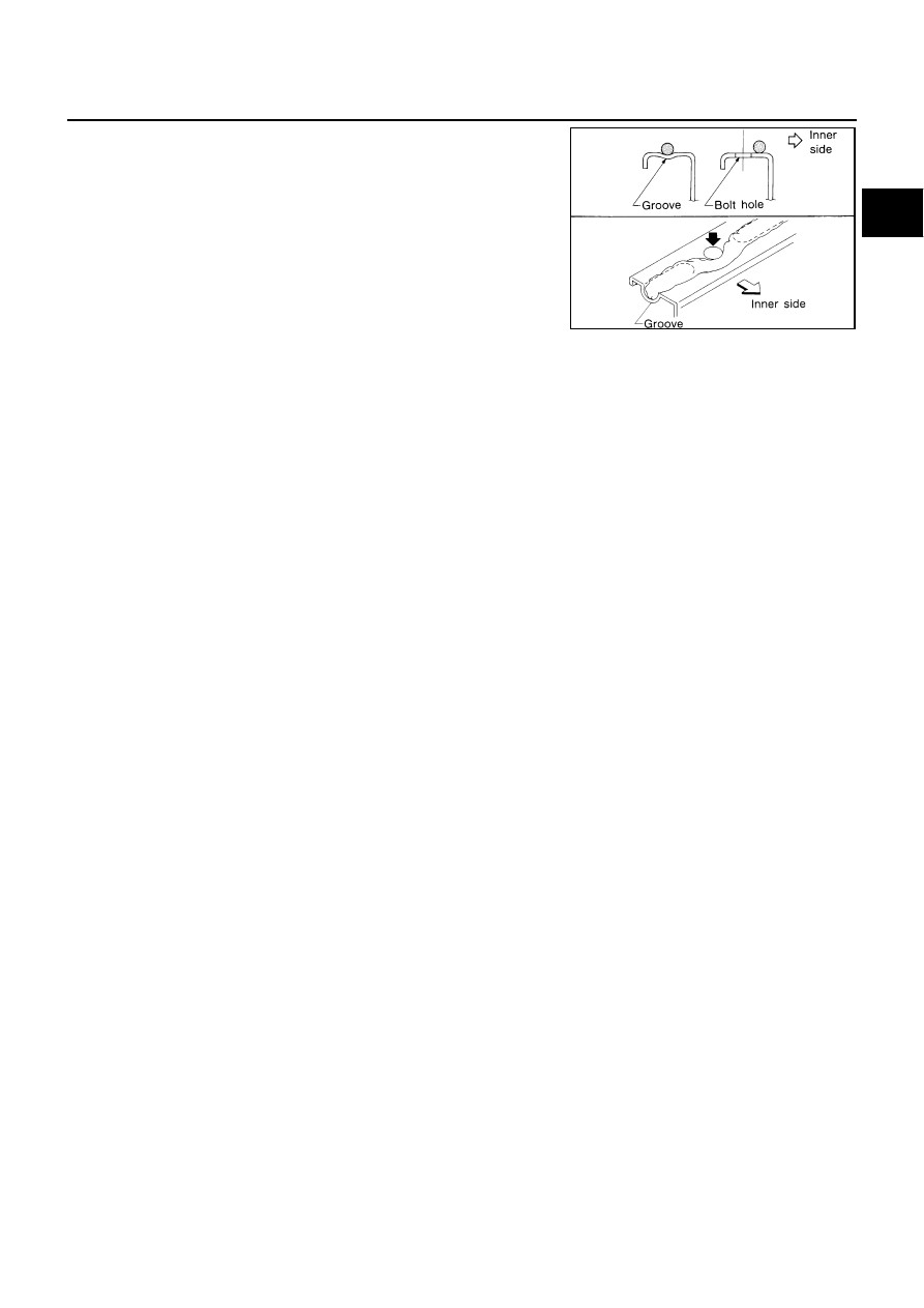
●
As for bolt holes, normally apply liquid gasket inside the
holes. Occasionally, it should be applied outside the holes.
Make sure to read the text of this manual.
●
Within 5 minutes of liquid gasket application, install the mating
component.
●
If liquid gasket protrudes, wipe it off immediately.
●
Do not retighten mounting bolts or nuts after the installation.
●
After 30 minutes or more have passed from the installation, fill
engine oil and engine coolant.
CAUTION:
If there are specific instructions in this manual, observe
them.
SEM159F