Nissan Murano Z50 (2006 year). Manual - part 120
ROOF RAIL
EI-29
C
D
E
F
G
H
J
K
L
M
A
B
EI
Revision: 2006 August
2006 Murano
ROOF RAIL
PFP:73820
Removal and Installation
NIS001EA
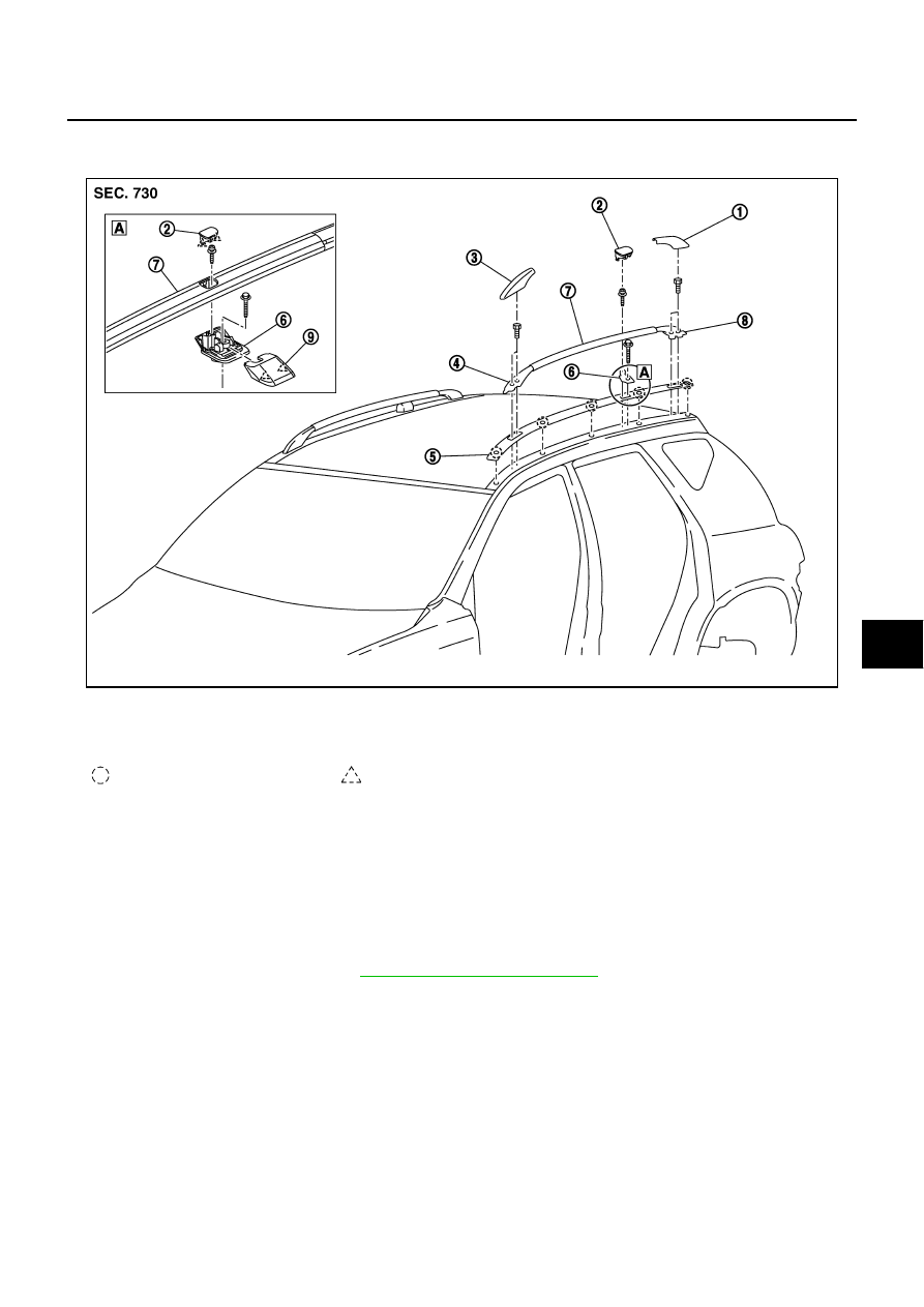
REMOVAL
1.
Remove roof rail front cover and rear cover.
2.
Remove roof rail center cap.
3.
Remove roof rail front/rear leg mounting bolts and remove roof rail center mounting bolt.
4.
Remove roof rail assembly.
5.
Remove roof rail center cover.
6.
Remove roof rail center leg mounting bolt and remove roof center leg.
7.
Remove roof side molding. Refer to
EI-28, "Removal and Installation"
INSTALLATION
Install in the reverse order of removal.
CAUTION:
Match the position to location pin and assembly center leg and rail assembly.
PIIB7407E
1.
Roof rail rear cover
2.
Roof rail center cap
3.
Roof rail front cover
4.
Roof rail front leg
5.
Roof side molding
6.
Roof rail center leg
7.
Roof rail assembly
8.
Roof rail rear leg
9.
Roof rail center cover
Clip
Pawl