Nissan Murano Z50 (2006 year). Manual - part 111
DTC P2100, P2103 THROTTLE CONTROL MOTOR RELAY
EC-555
C
D
E
F
G
H
I
J
K
L
M
A
EC
Revision: 2006 August
2006 Murano
Specification data are reference values and are measured between each terminal and ground.
Pulse signal is measured by CONSULT-II.
CAUTION:
Do not use ECM ground terminals when measuring input/output voltage. Doing so may result in dam-
age to the ECM's transistor. Use a ground other than ECM terminals, such as the ground.
: Average voltage for pulse signal (Actual pulse signal can be confirmed by oscilloscope.)
Diagnostic Procedure
NBS0037R
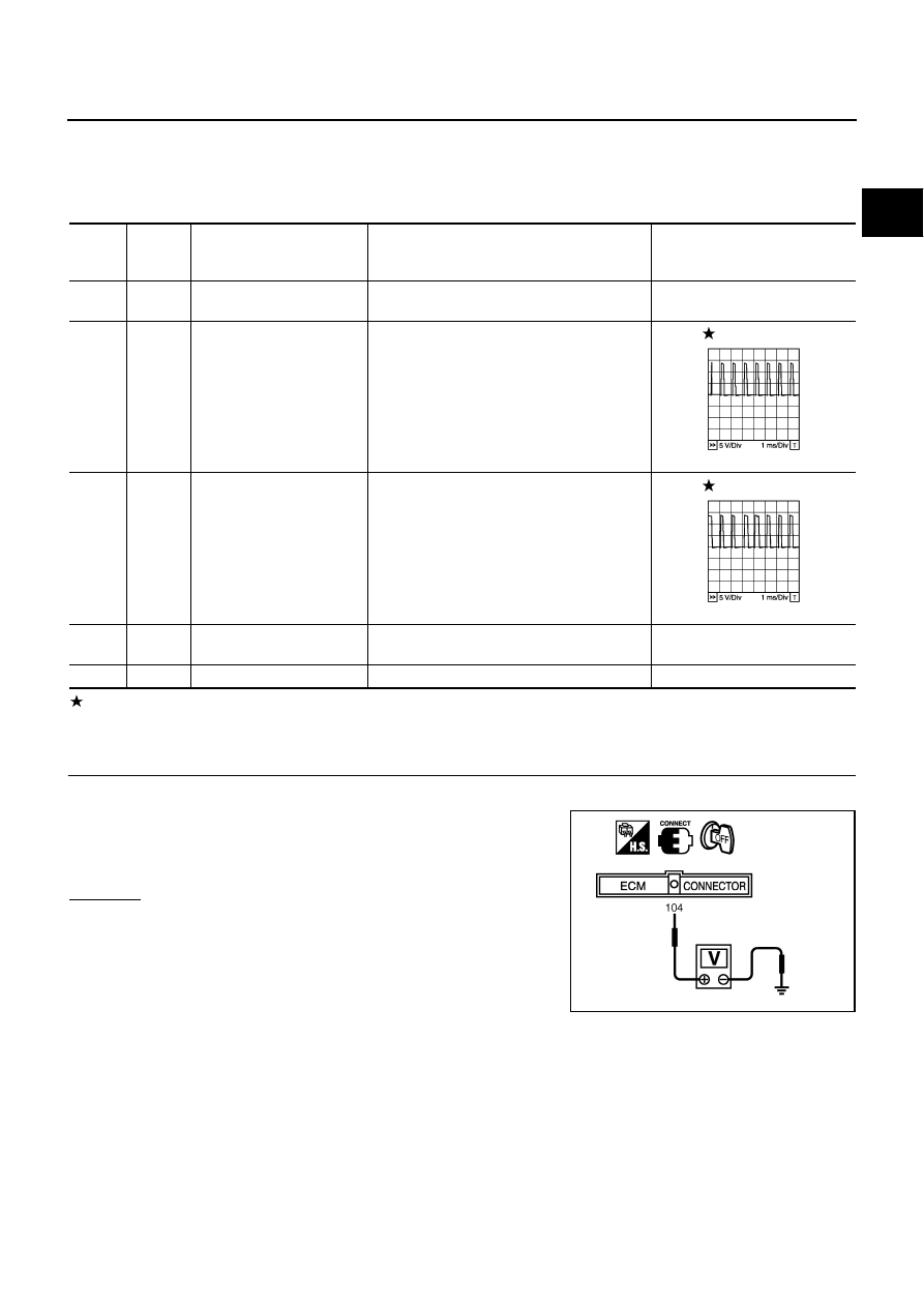
1.
CHECK THROTTLE CONTROL MOTOR RELAY POWER SUPPLY CIRCUIT-I
1.
Turn ignition switch OFF.
2.
Check voltage between ECM terminal 104 and ground with
CONSULT-II or tester.
OK or NG
OK
>> GO TO 5.
NG
>> GO TO 2.
TER-
MINAL
NO.
WIRE
COLOR
ITEM
CONDITION
DATA (DC Voltage)
3
R
Throttle control motor relay
power supply
[Ignition switch: ON]
BATTERY VOLTAGE
(11 - 14V)
4
G
Throttle control motor
(Close)
[Ignition switch: ON]
●
Engine stopped
●
Shift lever: D
●
Accelerator pedal: Fully released
0 - 14V
5
R
Throttle control motor
(Open)
[Ignition switch: ON]
●
Engine stopped
●
Shift lever: D
●
Accelerator pedal: Fully depressed
0 - 14V
104
P/L
Throttle control motor relay
[Ignition switch: OFF]
BATTERY VOLTAGE
(11 - 14V)
[Ignition switch: ON]
0 - 1.0V
PBIB1104E
PBIB1105E
Voltage: Battery voltage
PBIB1171E