Nissan Murano Z50 (2006 year). Manual - part 88
DTC P0101 MAF SENSOR
EC-187
C
D
E
F
G
H
I
J
K
L
M
A
EC
Revision: 2006 August
2006 Murano
DTC P0101 MAF SENSOR
PFP:22680
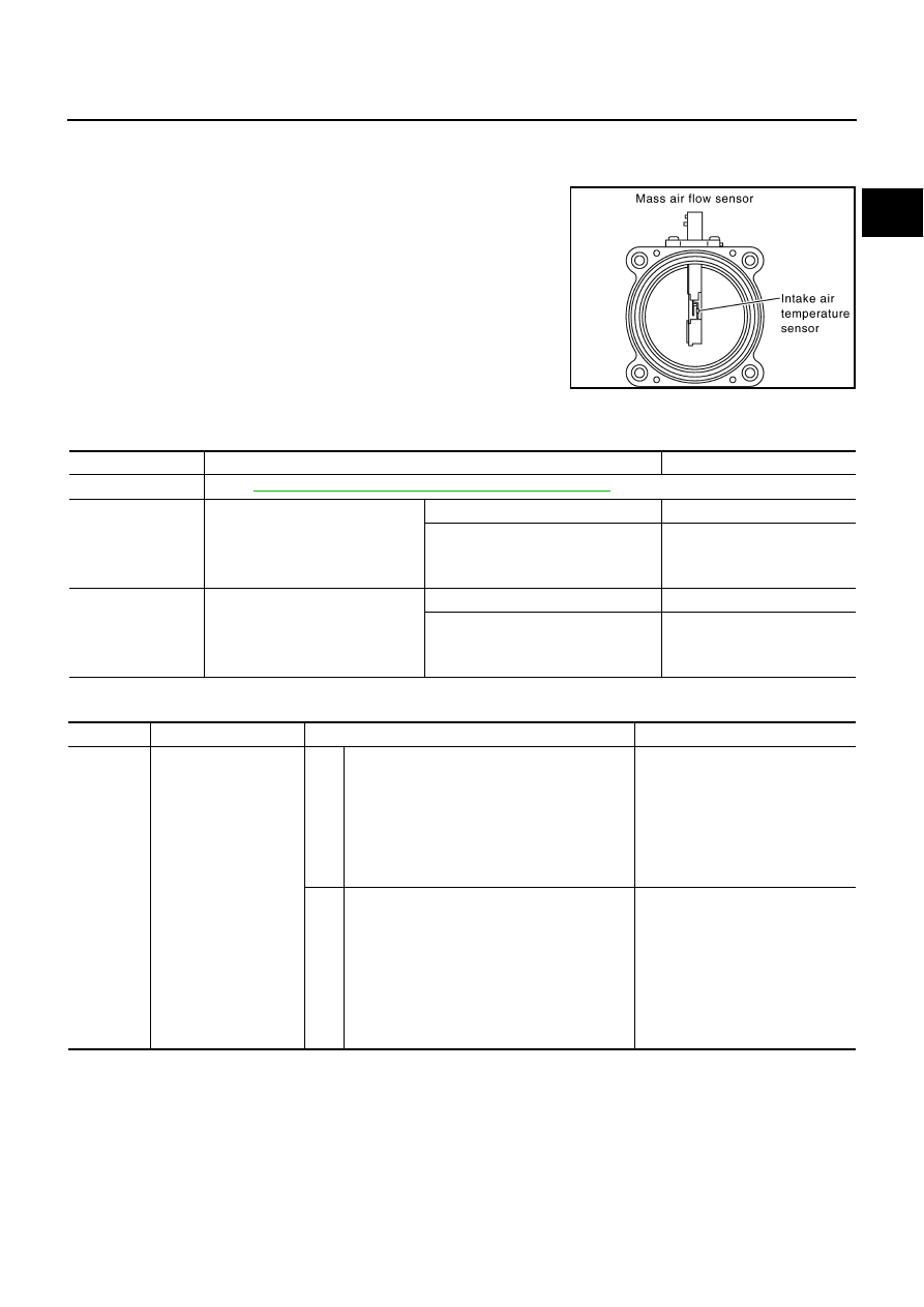
Component Description
NBS0030K
The mass air flow sensor is placed in the stream of intake air. It mea-
sures the intake flow rate by measuring a part of the entire intake
flow. The mass air flow sensor controls the temperature of the hot
wire to a certain amount. The heat generated by the hot wire is
reduced as the intake air flows around it. The more air, the greater
the heat loss.
Therefore, the electric current supplied to hot wire is changed to
maintain the temperature of the hot wire as air flow increases. The
ECM detects the air flow by means of this current change.
CONSULT-II Reference Value in Data Monitor Mode
NBS0030L
Specification data are reference values.
On Board Diagnosis Logic
NBS0030M
PBIB1604E
MONITOR ITEM
CONDITION
SPECIFICATION
MAS A/F SE-B1
●
See
EC-132, "TROUBLE DIAGNOSIS - SPECIFICATION VALUE"
.
CAL/LD VALUE
●
Engine: After warming up
●
Shift lever: P or N
●
Air conditioner switch: OFF
●
No load
Idle
5% - 35%
2,500 rpm
5% - 35%
MASS AIRFLOW
●
Engine: After warming up
●
Shift lever: P or N
●
Air conditioner switch: OFF
●
No load
Idle
2.0 - 6.0 g·m/s
2,500 rpm
7.0 - 20.0 g·m/s
DTC No.
Trouble diagnosis name
DTC detecting condition
Possible cause
P0101
0101
Mass air flow sensor cir-
cuit range/performance
A)
A high voltage from the sensor is sent to ECM
under light load driving condition.
●
Harness or connectors
(The sensor circuit is open or
shorted.)
●
Mass air flow sensor
●
EVAP control system pressure
sensor
●
Intake air temperature sensor
B)
A low voltage from the sensor is sent to ECM
under heavy load driving condition.
●
Harness or connectors
(The sensor circuit is open or
shorted.)
●
Intake air leaks
●
Mass air flow sensor
●
EVAP control system pressure
sensor
●
Intake air temperature sensor