Nissan Murano Z50 (2006 year). Manual - part 77
INDEX FOR DTC
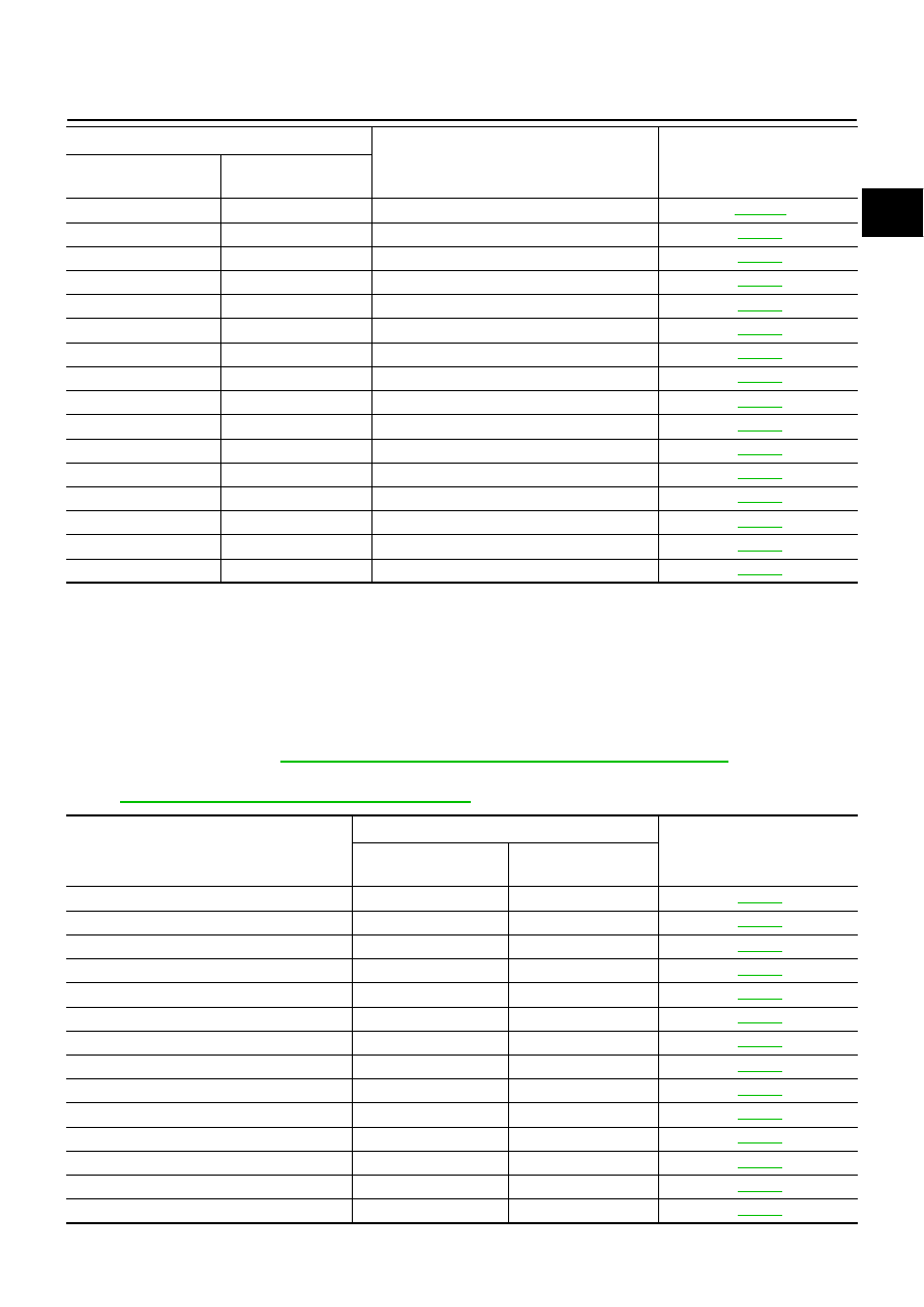
EC-11
C
D
E
F
G
H
I
J
K
L
M
A
EC
Revision: 2006 August
2006 Murano
*1: 1st trip DTC No. is the same as DTC No.
*2: This number is prescribed by SAE J2012.
*3: In Diagnostic Test Mode II (Self-diagnostic results), this number is controlled by NISSAN.
*4: The troubleshooting for this DTC needs CONSULT-II.
*5: When the fail-safe operations for both self-diagnoses occur at the same time, the MIL illuminates.
Alphabetical Index
NBS003F2
NOTE:
●
If DTC U1000 or U1001 is displayed with other DTC, first perform the trouble diagnosis for DTC
U1000, U1001. Refer to
EC-152, "DTC U1000, U1001 CAN COMMUNICATION LINE"
.
●
If DTC U1010 is displayed with other DTC, first perform the trouble diagnosis for DTC U1010. Refer
to
EC-155, "DTC U1010 CAN COMMUNICATION"
P1778
1778
STEP MOTR FNC
P1800
1800
VIAS S/V CIRC
P1805
1805
BRAKE SW/CIRCUIT
P2100
2100
ETC MOT PWR
P2101
2101
ETC FUNCTION/CIRC
P2103
2103
ETC MOT PWR
P2118
2118
ETC MOT
P2119
2119
ETC ACTR
P2122
2122
APP SEN 1/CIRC
P2123
2123
APP SEN 1/CIRC
P2127
2127
APP SEN 2/CIRC
P2128
2128
APP SEN 2/CIRC
P2135
2135
TP SENSOR
P2138
2138
APP SENSOR
P2A00
2A00
A/F SENSOR1 (B1)
P2A03
2A03
A/F SENSOR1 (B2)
DTC*
1
Items
(CONSULT-II screen terms)
Reference page
CONSULT-II
GST*
2
ECM*
3
Items
(CONSULT-II screen terms)
DTC*
1
Reference page
CONSULT-II
GST*
2
ECM*
3
A/F SEN1 HTR (B1)
P0031
0031
A/F SEN1 HTR (B1)
P0032
0032
A/F SEN1 HTR (B2)
P0051
0051
A/F SEN1 HTR (B2)
P0052
0052
A/F SENSOR1 (B1)
P0130
0130
A/F SENSOR1 (B1)
P0131
0131
A/F SENSOR1 (B1)
P0132
0132
A/F SENSOR1 (B1)
P0133
0133
A/F SENSOR1 (B1)
P2A00
2A00
A/F SENSOR1 (B2)
P0150
0150
A/F SENSOR1 (B2)
P0151
0151
A/F SENSOR1 (B2)
P0152
0152
A/F SENSOR1 (B2)
P0153
0153
A/F SENSOR1 (B2)
P2A03
2A03