Nissan Murano Z50 (2006 year). Manual - part 69


  Index      Manuals     Nissan Murano Z50 (2006 year) - Service and Repair Manual


Search            copyright infringement  


Content      ..     67      68      69      70     ..


Nissan Murano Z50 (2006 year). Manual - part 69


SHIFT CONTROL SYSTEM

CVT-209

D

E

F

G

H

I

J

K

L

M

A

B

CVT

Revision: 2006 August

2006 Murano

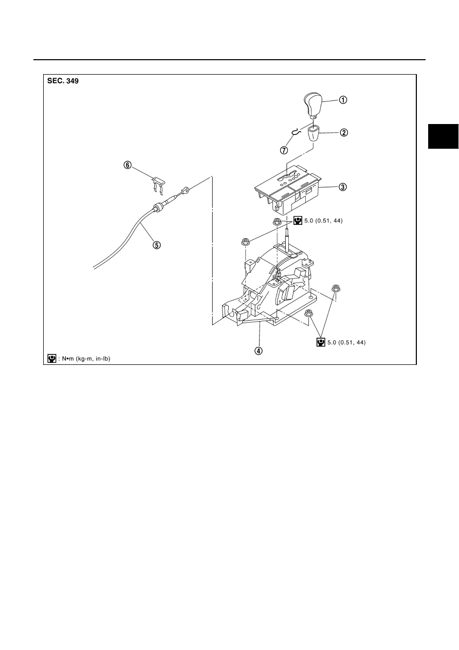
CONTROL DEVICE COMPONENTS (WITHOUT MANUAL MODE)

1.

Selector lever knob

2.

Knob cover

3.

A/T console finisher

4.

Control device assembly

5.

Control cable

6.

Lock plate

7.

Lock pin

SCIA6464E

CVT-210

SHIFT CONTROL SYSTEM

Revision: 2006 August

2006 Murano

CONTROL CABLE COMPONENTS

Refer to the figure below for control cable removal and installation procedure. 

REMOVAL

1.

Remove knob cover below selector lever downward.

2.

Pull lock pin out of selector lever knob.

3.

Remove selector lever knob.

4.

Remove A/T console finisher.

Refer to 

IP-18, "Removal and Installation"

 .

5.

Remove console box assembly.

Refer to 

IP-18, "Removal and Installation"

 .

6.

Disconnect control cable of control device.

7.

Disconnect control device harness connector.

1.

Selector lever knob

2.

Control device assembly

3.

Lock plate

4.

Bracket

5.

Control cable

6.

Lock plate

7.

Transaxle assembly

SCIA5988E

SCIA4377E

SCIA5963E

SHIFT CONTROL SYSTEM

CVT-211

D

E

F

G

H

I

J

K

L

M

A

B

CVT

Revision: 2006 August

2006 Murano

8.

Remove control device assembly.

INSTALLATION

 Note the following, and install in the reverse order of removal.

The knurled surface of rib should be upward when installing the
control cable to the control device assembly. And insert the con-
trol cable securely.

After installation is completed, adjust and check CVT position.
Refer to 

CVT-211, "Adjustment of CVT Position"

  an

CVT-212,

"Checking of CVT Position"

 .

Adjustment of CVT Position

NCS00199

1.

Place selector lever in “P” position.

2.

Loosen control cable nut and place manual lever in “P” position.

CAUTION:

Turn wheels more than 1/4 rotations and apply the park
lock.

3.

Hold the control cable at the end. Push and pull it twice or three
times, and then push it with a load of 9.8 N (approximately 1 kg,
2.2 lb). Temporarily tighten the control cable nut with the control
cable loose.

4.

Connect control cable on manual lever.

CAUTION:

No application of a force to the manual lever.

5.

Tighten control cable nut.

CAUTION:

Fix the manual lever when tightening.

SCIA5964E

SCIA5990E

: 13 N·m (1.3 kg-m, 10 ft-lb)

SCIA2001E

CVT-212

SHIFT CONTROL SYSTEM

Revision: 2006 August

2006 Murano

Checking of CVT Position

NCS0019A

1.

Place selector lever in “P” position, and turn ignition switch ON. (Do not start engine.)

2.

Make sure selector lever can be shifted to other than “P” posi-
tion when brake pedal is depressed. Also make sure selector
lever can be shifted from “P” position only when brake pedal is
depressed.

3.

Move the selector lever and check for excessive effort, sticking,
noise or rattle.

4.

Confirm the selector lever stops at each position with the feel of
engagement when it is moved through all the positions. Check
whether or not the actual position the selector lever is in
matches the position shown by the shift position indicator and
the transaxle body.

5.

The method of operating the selector lever to individual posi-
tions correctly should be as shown in the figure.

6.

Confirm the back-up lamps illuminate only when selector lever is
placed in the “R” position. Confirm the back-up lamps do not illu-
minate when the selector lever is pushed toward the “R” position
side with the gear position remained in the “P” or “N” position.

7.

Confirm the engine can only be started with the selector lever in
the “P” and “N” positions.

8.

Make sure transaxle is locked completely in “P” position.

9.

When selector lever is set to manual shift gate, make sure man-
ual mode is displayed on combination meter.
Shift selector lever to “+” and “-” sides, and make sure set shift position changes.

SCIA8112E

SCIA8113E

CVT SHIFT LOCK SYSTEM

CVT-213

D

E

F

G

H

I

J

K

L

M

A

B

CVT

Revision: 2006 August

2006 Murano

CVT SHIFT LOCK SYSTEM

PFP:00000

Description

NCS0019B

The electrical key interlock mechanism also operates as a shift lock:
With the ignition switch turned to ON, the selector lever cannot be shifted from “P” (parking) to any other
position unless the brake pedal is depressed.
With the key removed, the selector lever cannot be shifted from “P” to any other position.
The key cannot be removed unless the selector lever is placed in “P”.

The shift lock and key interlock mechanisms are controlled by the ON-OFF operation of the shift lock sole-
noid and by the operation of the rotator and slider located inside the key cylinder, respectively.

Shift Lock System Electrical Parts Location

NCS0019C

NOTE:
This emergency lever can be used when battery is off ignition key cannot be removed. In the situation like this,
by operating this lever, ignition key can be removed.

SCIA8159E

CVT-214

CVT SHIFT LOCK SYSTEM

Revision: 2006 August

2006 Murano

Wiring Diagram — CVT — SHIFT (With Intelligent Key)

NCS0019D

TCWB0261E

CVT SHIFT LOCK SYSTEM

CVT-215

D

E

F

G

H

I

J

K

L

M

A

B

CVT

Revision: 2006 August

2006 Murano

TCWB0065E

CVT-216

CVT SHIFT LOCK SYSTEM

Revision: 2006 August

2006 Murano

Wiring Diagram — CVT — SHIFT (Without Intelligent Key)

NCS0019E

TCWB0262E

CVT SHIFT LOCK SYSTEM

CVT-217

D

E

F

G

H

I

J

K

L

M

A

B

CVT

Revision: 2006 August

2006 Murano

TCWB0067E

CVT-218

CVT SHIFT LOCK SYSTEM

Revision: 2006 August

2006 Murano

Shift Lock Control Unit Reference Values

NCS0019F

SHIFT LOCK HARNESS CONNECTOR TERMINALS LAYOUT

SHIFT LOCK CONTROL UNIT INSPECTION TABLE

Shift lock control unit terminal data are reference values, measured between each terminal and ground.

NOTE:
Take care that the pointer swings only momentarily because the output time is so short. If the inspection is done with an oscilloscope, it
should be observed that the power source voltage lasts for 3.5 to 10 ms.

SCIA2004E

Terminal

(Wire color)

Item

Condition

Judgment standard

1

(R/Y)

Power source

Always

Battery voltage

2

(L)

Detention switch (for 
key)

When selector lever is not in “P” position with key 
inserted or ignition knob switch pushed.

Battery voltage

When selector lever is in “P” position with key 
inserted.

Approx. 0 V

3

(L/W)

Detention switch (for 
shift)

When selector lever is not in “P” position.

Battery voltage

When selector lever is in “P” position.

Approx. 0 V

4

(R/G)

Stop lamp switch

When brake pedal is depressed

Battery voltage

When brake pedal is released

Approx. 0 V

5

(V/W)

Vehicle speed signal 
(8pulse signal)

Speed meter is operated

Refer to 

DI-14, "Terminals and Refer-

ence Value for Unified Meter and A/C 
Amp."

 .

6

(G)

Ignition signal

Ignition switch: OFF

Approx. 0 V 

Ignition switch: ON

Battery voltage

7

(R/L)

Shift lock solenoid

When selector lever is in “P” position, brake 
pedal is depressed, and ignition switch is ON.

When selector lever is not in “P” position, igni-
tion switch is ON, and vehicle speed is 10 km/h 
(6 MPH) or less.

For 3 minutes after selector lever is not in “P” 
position, vehicle speed is 10 km/h (6 MPH) or 
less, and ignition switch is ON 

 OFF.

Approx. 0 V

Except the above

Battery voltage

8

(B)

Ground

Approx. 0 V

9

(V)

Key lock solenoid

When selector lever is not in “P” position.

Battery voltage for approx. 0.1 sec. 
(Note)

When selector lever is in “P” position.

Approx. 0 V

10

(W/B)

Key unlock solenoid

When selector lever is in “P” position with ignition 
switch OFF.

Battery voltage for approx. 0.1 sec. 
(Note)

When selector lever is not in “P” position with igni-
tion switch OFF.

Approx. 0 V

CVT SHIFT LOCK SYSTEM

CVT-219

D

E

F

G

H

I

J

K

L

M

A

B

CVT

Revision: 2006 August

2006 Murano

Component Inspection

NCS0019G

SHIFT LOCK SOLENOID

Check operation by applying battery voltage to the CVT device har-
ness connector.

CAUTION:

Be sure to apply the voltage of the correct polarity to the
respective terminals. Otherwise, the part may be damaged.

DETENTION SWITCH (FOR KEY)

Check continuity between terminals of the CVT device harness con-
nector.

DETENTION SWITCH (FOR SHIFT)

Check continuity between terminals of the CVT device harness con-
nector.

KEY LOCK SOLENOID (WITH INTELLIGENT KEY)
Key Lock 

Check operation by applying battery voltage to key switch and igni-
tion knob switch harness connector.

CAUTION:

Be careful not to cause burnout of the harness.

Connector

Terminal

M57

9 (Battery voltage) - 10 (Ground)

SCIA2005E

Condition

Connector

Terminal

Continuity

When selector lever is in “P” 
position.

M57

5 - 6

No

When selector lever is not in 
“P” position.

Yes

SCIA2006E

Condition

Connector

Terminal

Continuity

When selector lever is in “P” 
position.

M57

13 - 14

No

When selector lever is not in 
“P” position.

Yes

SCIA2046E

Connector

Terminal

M118

6 (Battery voltage) - 5 (Ground)

SCIA6152E

CVT-220

CVT SHIFT LOCK SYSTEM

Revision: 2006 August

2006 Murano

Key Unlock

Check operation by applying battery voltage to key switch and igni-
tion knob switch harness connector.

CAUTION:

Be careful not to cause burnout of the harness.

KEY LOCK SOLENOID (WITHOUT INTELLIGENT KEY)
Key Lock 

Check operation by applying battery voltage to key switch harness
connector.

CAUTION:

Be careful not to cause burnout of the harness.

Key Unlock

Check operation by applying battery voltage to key switch harness
connector.

CAUTION:

Be careful not to cause burnout of the harness.

KEY SWITCH (WITH INTELLIGENT KEY)

Check continuity between terminals of the key switch and ignition
knob switch harness connector.

Connector

Terminal

M118

5 (Battery voltage) - 6 (Ground)

SCIA6151E

Connector

Terminal

M28

1 (Battery voltage) - 2 (Ground)

SCIA6460E

Connector

Terminal

M28

2 (Battery voltage) - 1 (Ground)

SCIA6461E

Condition

Connector

Terminal

Continuity

Key inserted

M118

3 - 4

Yes

Key withdrawn

No

SCIA6153E

CVT SHIFT LOCK SYSTEM

CVT-221

D

E

F

G

H

I

J

K

L

M

A

B

CVT

Revision: 2006 August

2006 Murano

KEY SWITCH (WITHOUT INTELLIGENT KEY)

Check continuity between terminals of the key switch harness con-
nector.

IGNITION KNOB SWITCH (WITH INTELLIGENT KEY)

Check continuity between terminals of the key switch and ignition
knob switch harness connector.

STOP LAMP SWITCH

Check continuity between terminals of the stop lamp switch harness
connector.

Check stop lamp switch after adjusting brake pedal. Refer to 

BR-6,

"Inspection and Adjustment"

 .

Condition

Connector

Terminal

Continuity

Key inserted

M28

3 - 4

Yes

Key withdrawn

No

SCIA6462E

Condition

Connector

Terminal

Continuity

Pushed

M118

1 - 2

Yes

Released

No

SCIA6671E

Condition

Connector

Terminal

Continuity

When brake pedal is depressed

E116

3 - 4

Yes

When brake pedal is released

No

SCIA2126E

CVT-222

AIR BREATHER HOSE

Revision: 2006 August

2006 Murano

AIR BREATHER HOSE

PFP:31098

Removal and Installation

NCS0019H

Refer to the figure below for air breather hose removal and installation procedure. 

CAUTION:

Securely insert the hose into the air breather until it touches the bottom. 

SCIA2284E

DIFFERENTIAL SIDE OIL SEAL

CVT-223

D

E

F

G

H

I

J

K

L

M

A

B

CVT

Revision: 2006 August

2006 Murano

DIFFERENTIAL SIDE OIL SEAL

PFP:33111

Removal and Installation

NCS0019I

COMPONENTS

REMOVAL

1.

Remove drive shaft assembly. Refer to 

FAX-7, "FRONT DRIVE

SHAFT"

 .

2.

Remove transfer from transaxle assembly. (AWD models)
Refer to 

TF-52, "Removal and Installation"

 .

3.

Remove differential side oil seals using a flat-bladed screw-
driver.

CAUTION:

Be careful not to scratch transaxle case or converter hous-
ing.

1.

Transaxle assembly

2.

Differential side oil seal

SCIA2408E

SCIA2412E

CVT-224

DIFFERENTIAL SIDE OIL SEAL

Revision: 2006 August

2006 Murano

INSTALLATION

1.

As shown below, use a drift to drive the differential side oil seals
into the case until it is flush. Refer to dimensions A.

Unit: mm (in)

NOTE:
The differential side oil seals pulling direction is used as the ref-
erence.

Drift to be used:

CAUTION:

Do not reuse differential side oil seals.

When installing differential side oil seals, apply NISSAN CVT Fluid NS-2.

2.

Reinstall any part removed.

CAUTION:

If lubricant leak has occurred, after finishing work, check fluid level. Refer to 

CVT-15, "Checking

CVT Fluid"

 .

Dimensions A

±

 0.5 (0 

±

 0.020)

SCIA2411E

Location

2WD models

AWD models

Transaxle case side (left)
Tool number: A
(Kent-Moore No.)

(J-47244)

(J-47244)

Converter housing side 
(right)
Tool number: A
(Kent-Moore No.)

ST33400001

(J-47005)

(J-34339-A)

SCIA6583E


Content      ..     67      68      69      70     ..